00193891-0702_AI_LP_Barcode_DE+EN.pdf - 第178页
2 PCB barcode scanner assembly instructions SIPLACE 2.7 Installing the PCB barcode scanner 10/2009 Edition 178 2.7.4 SIPLACE F4/F5/F5 HM /S-20/S-23/S-25 HM/S-27 HM 2 It is essential to disconnect the automatic p lacement…

SIPLACE 2 PCB barcode scanner assembly instructions
10/2009 Edition 2.7 Installing the PCB barcode scanner
177
Attaching the warning label 2
: Attach the three laser warning labels to the Makrolon window on the input belt.
Th
e labels are needed because a laser class 2 sensor
beam that is directed upwards while the
machine is in use could be directed outside.
2
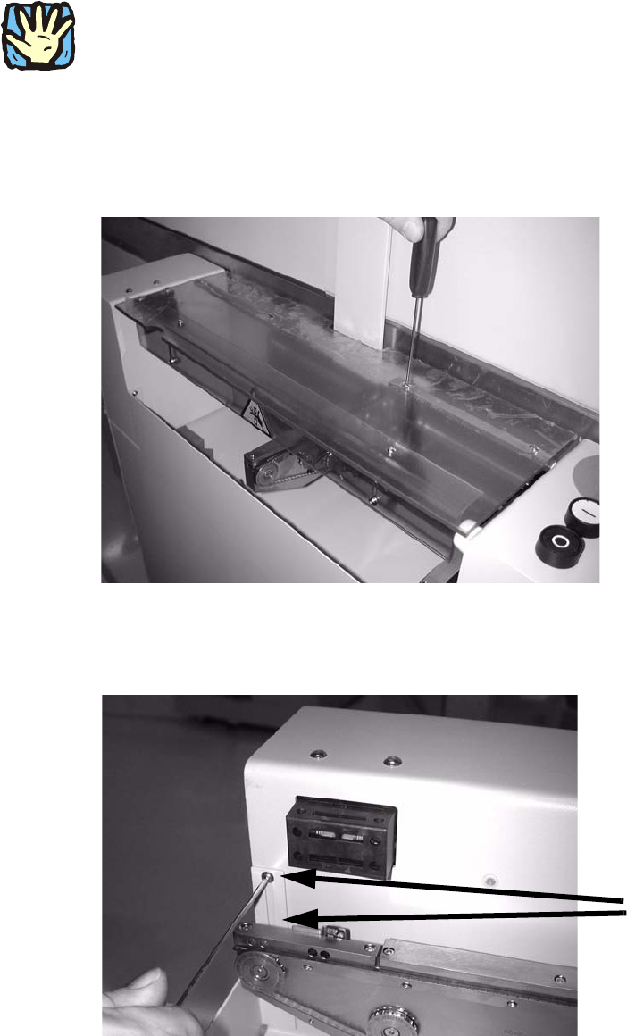
: Tighten any screws that are still loose.
: Refit and close all removed panels, covers and protective hoods.
: Set the distances between the 1D barcode scanner an
d the PCB so that the barcodes are read
reliably. This is achieved by moving the cross-rails up or down in the slots (see scanning field
diagram in
Chapter 2.11.4).
: For the 2D barcode scanner, set the dist
ance to exactly 60 mm +/- 1 mm.
Use the adjusting gauge provided.
The 2D scanner only works in this focus range.
Distance from 2D barcode scanner
to PCB: 60 mm +/- 1 mm.
The SICK software (version > 4.1)
can be used to check the setting.2
Setting gauge
2
2 PCB barcode scanner assembly instructions SIPLACE
2.7 Installing the PCB barcode scanner 10/2009 Edition
178
2.7.4 SIPLACE F4/F5/F5 HM/S-20/S-23/S-25 HM/S-27 HM
2
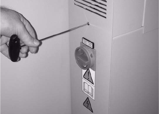
It is essential to disconnect the automatic placement system from the mains during retrofitting as
otherwise the main switch would be live while the work was being done. 2
2
2.7.4.1 Preparatory work
: Unscrew the hinge on one side of the PCB feeder protective cover and remove it.
2
2
: Loosen the two screws on the front left side panel.
2 screws
2
2
SIPLACE 2 PCB barcode scanner assembly instructions
10/2009 Edition 2.7 Installing the PCB barcode scanner
179
: Remove the extension kit end wall on the main switch side.
2
2