00193891-0702_AI_LP_Barcode_DE+EN.pdf - 第179页
SIPLACE 2 PCB barcode scanner assembly instructions 10/2009 Edition 2.7 Installing the PCB barcode scanner 179 : Remove the extension kit end wa ll on the main switch side. 2 2
2 PCB barcode scanner assembly instructions SIPLACE
2.7 Installing the PCB barcode scanner 10/2009 Edition
178
2.7.4 SIPLACE F4/F5/F5 HM/S-20/S-23/S-25 HM/S-27 HM
2
It is essential to disconnect the automatic placement system from the mains during retrofitting as
otherwise the main switch would be live while the work was being done. 2
2
2.7.4.1 Preparatory work
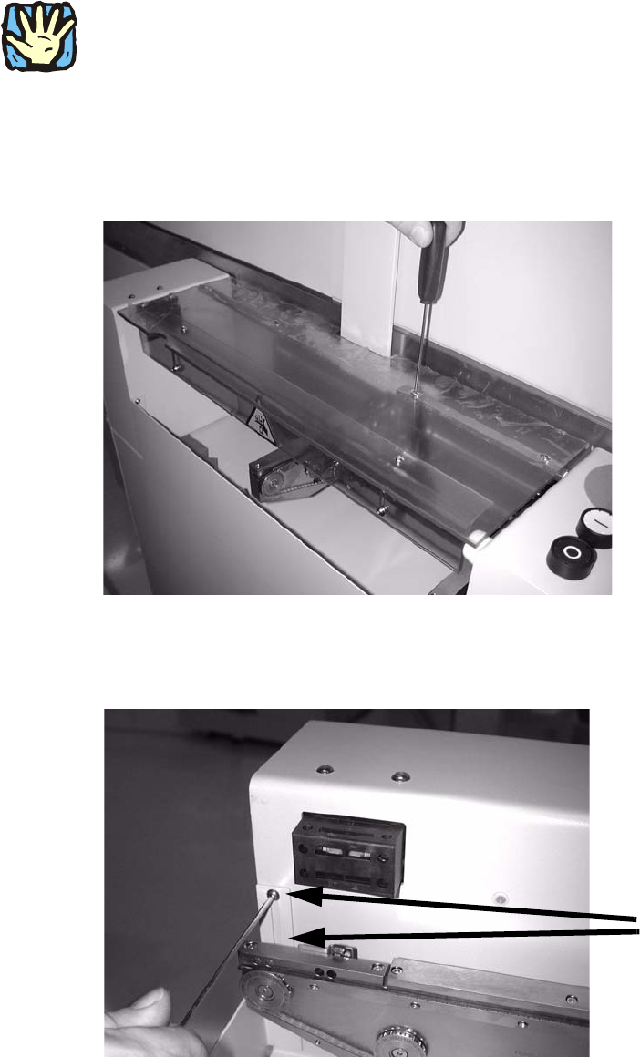
: Unscrew the hinge on one side of the PCB feeder protective cover and remove it.
2
2
: Loosen the two screws on the front left side panel.
2 screws
2
2
SIPLACE 2 PCB barcode scanner assembly instructions
10/2009 Edition 2.7 Installing the PCB barcode scanner
179
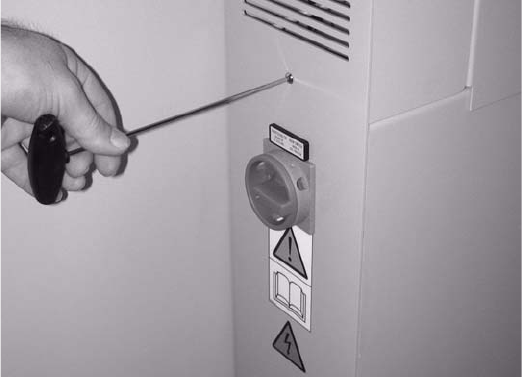
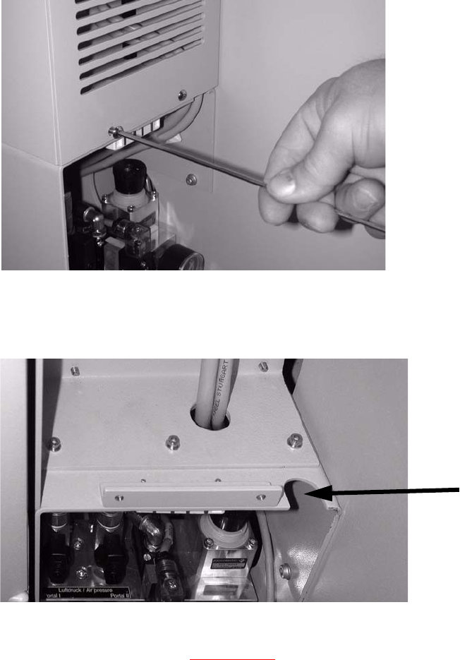
: Remove the extension kit end wall on the main switch side.
2
2
2 PCB barcode scanner assembly instructions SIPLACE
2.7 Installing the PCB barcode scanner 10/2009 Edition
180
2.7.5 Provide cable penetration (not SIPLACE S-27 HM)
: Remove the grille on the right side of the machine (2 screws).
2
2
: Check that provision is made for cable penetration.
Cable penetration
2
: If no cable penetration slot is provided, do the work described in this section.
If it is provided, proceed to
Chapter 2.7.6 .
Tools required 2
– Power drill or cordless screwdriver
– Drill bit (10 mm)
– Sliding gauge
– Compass saw or hacksaw.