00193891-0702_AI_LP_Barcode_DE+EN.pdf - 第196页
2 PCB barcode scanner assembly instructions SIPLACE 2.7 Installing the PCB barcode scanner 10/2009 Edition 196 : Affix the protective st icke r to the protective flap. This sticker is manda- tory for the 2D bar- code, as…
SIPLACE 2 PCB barcode scanner assembly instructions
10/2009 Edition 2.7 Installing the PCB barcode scanner
195
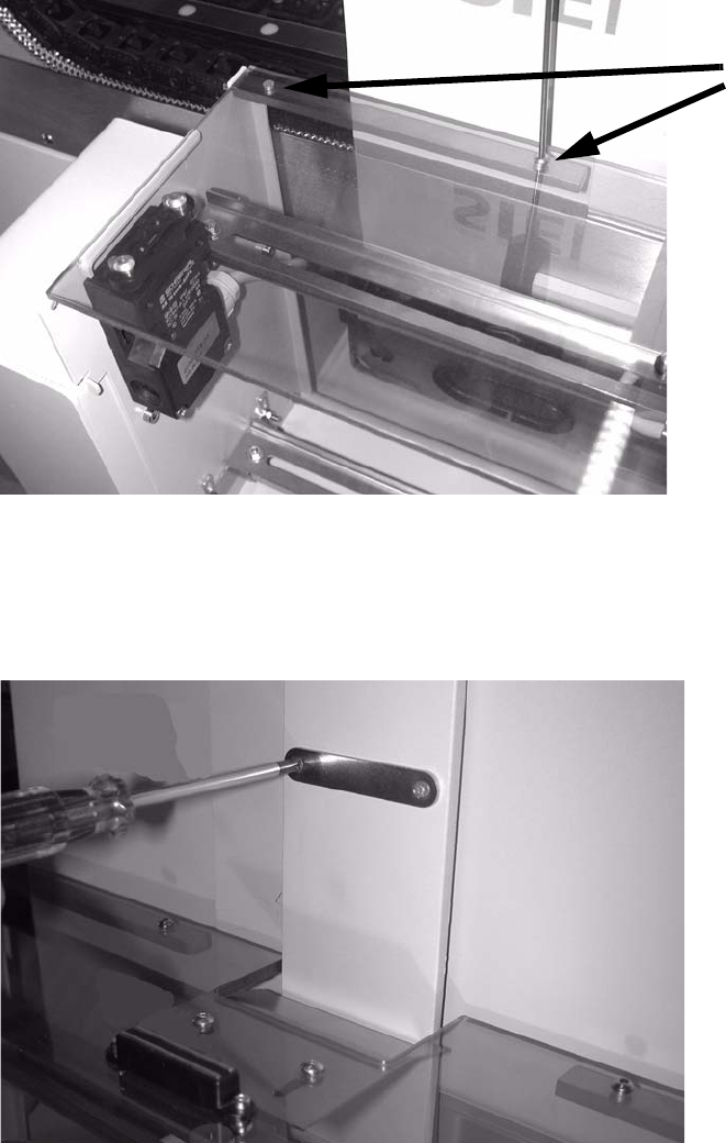
: Place the other hinge in the hole and screw the protective cover to the hinge.
2 screws
2
2
: Align the cover switch and actuator.
: Screw the oppo
site magnet plate onto the machine cross-member.
2
2
2
2
2
2 PCB barcode scanner assembly instructions SIPLACE
2.7 Installing the PCB barcode scanner 10/2009 Edition
196
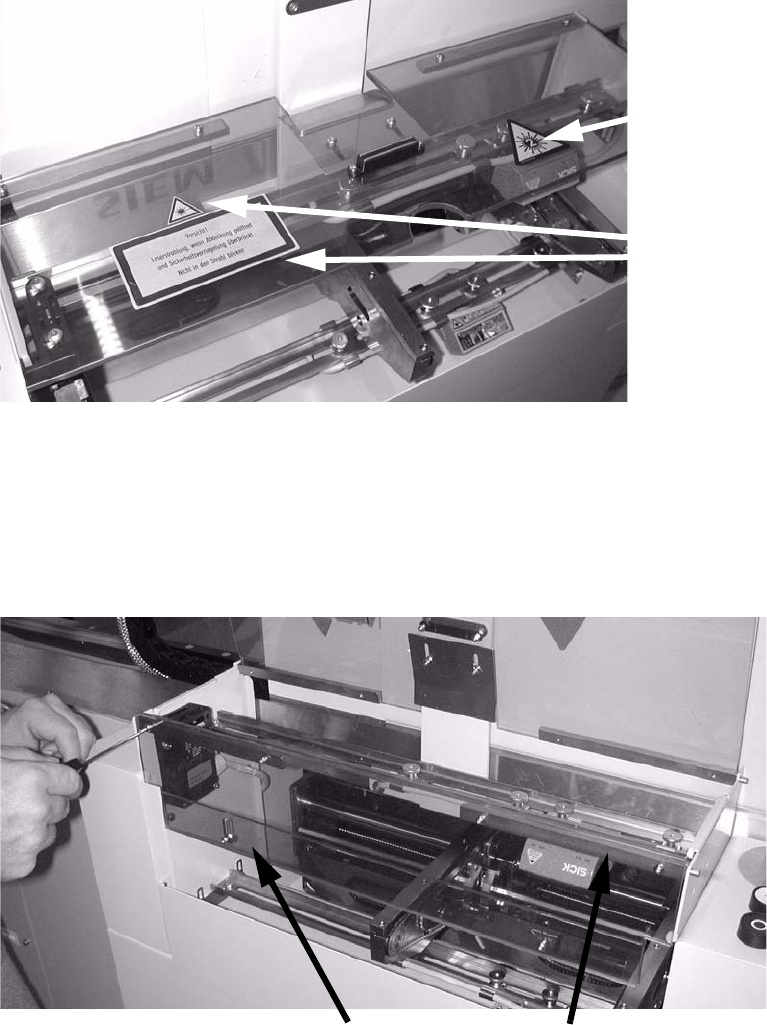
: Affix the protective sticker to the protective flap.
This sticker is manda-
tory for the 2D bar-
code, as this has a
class 2 laser.
Sticker.
2
: Screw the narrow Plexiglas strips onto the cover that is mounted at right angles over the PCB
feeder.
: Fit the front cover, once again premounting one hinge, then screwing the cover to the inserted
h
inge.
The plexiglas strips must be on the inside.
plexiglas strips
Hinges
2
: Tighten any screws that are still loose.
: Refit and close all removed panels, covers and protective hoods.
SIPLACE 2 PCB barcode scanner assembly instructions
10/2009 Edition 2.7 Installing the PCB barcode scanner
197
: Set the distances between the 1D barcode scanner and the PCB so that the barcodes are read
reliably.
This is achieved by moving the cross-rails up or down in the slots.
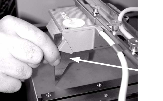
: For the 2D barcode scanner, set to exactly 85 m
m ± 1 mm. Use the setting gauge provided.
The 2D barcode scanner only works in this focus range.
Distance from 2D barcode scan-
ner
to PCB: 85 mm +/- 1 mm.
The SICK software (version >
4.1) can be used to check the set-
ting. 2
Setting gauge
2
2
2
2
2
2
2
2
2
2
2
2
2
2