00193891-0702_AI_LP_Barcode_DE+EN.pdf - 第223页
SIPLACE 2 PCB barcode scanner assembly instructions 10/2009 Edition 2.11 PCB barcode scanner configuration 223 2.1 1.6 Settings on the 1D barcode scanner The 1D barcode sca nner CL V41x or CL V42x is co nfigured using se…
2 PCB barcode scanner assembly instructions SIPLACE
2.11 PCB barcode scanner configuration 10/2009 Edition
222
2.11.5 Overview of the PCB barcode scanner configuration
Use the software (CLV 4.1) and operating instructions from SICK to configure the 1D or 2D bar-
code scanner. The instructions are attached to this training
folder and the software can be down-
loaded from the Service Competence Center.
Installation 1D- and 2D- PCB Bar code reader
1D Bar code reader
CLV 41x
1. Mounting Bar code reader
corresponding the retrofitting kit
for the respective Machine type.
2D Bar code reader
ICR 850
1D Bar code reader
CLV 42x
3.
Offline - Configuration of the PCB
Bar code reader together with the
CLV Software.
Note: No adjustment for the option traceability on the programming system necessary.
2.
Installation of the CLV Software
(Version 4.1) on a computer with
printer.
4. Print the bar code label which
configure the bar code reader
PCB Barcodereader 1 = 4 bar code
PCB Barcodereader 2-4 = 5 bar
code
4.
Download the configure parameter
to the 2D Bar code reader.
5.
Configure the PCB Bar code
reader on the Station.
6. Configure the PCB Bar code
reader on the programming system
LRU/LRL or Siplace Pro.
1. Mounting Bar code reader
corresponding the retrofitting kit
for the respective Machine type.
1. Mounting Bar code reader
corresponding the retrofitting kit
for the respective Machine type.
2.
Installation of the CLV Software
(Version 4.1) on a computer with
printer.
2.
Installation of the CLV Software
(Version 4.1) on a computer.
3.
Offline - Configuration of the PCB
Bar code reader together with the
CLV Software.
3.
Online - Configuration of the PCB
Bar code reader together with the
CLV Software.
4. Print the bar code label which
configure the bar code reader
PCB Barcodereader 1 = 7 bar code
PCB Barcodereader 2-4 = 8 bar
code
5.
Configure the PCB Bar code
reader on the Station.
5.
Configure the PCB Bar code
reader on the Station.
6. Configure the PCB Bar code
reader on the programming system
LRU/LRL or Siplace Pro.
6. Configure the PCB Bar code
reader on the programming system
LRU/LRL or Siplace Pro.
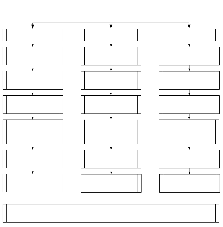
Fig. 2.11 - 7 Overview of the configuration of the various PCB barcode scanners
SIPLACE 2 PCB barcode scanner assembly instructions
10/2009 Edition 2.11 PCB barcode scanner configuration
223
2.11.6 Settings on the 1D barcode scanner
The 1D barcode scanner CLV41x or CLV42x is configured using several barcodes that are printed
on a sheet of paper. No online connection to the 1D barcode scanner is required.
The barcode is configured with the CLV software (version 4.1) from SICK.
NOTE:
The CLV software can be downloaded from the download center or from the Internet at
www.sick.de.
2.11.6.1 Configuring the barcodes for the 1D barcode scanner
: Install the CLV software by running CLVsetup.exe.
: The installation is dialog-driven
. Remember to select the unit " Inch or metric".
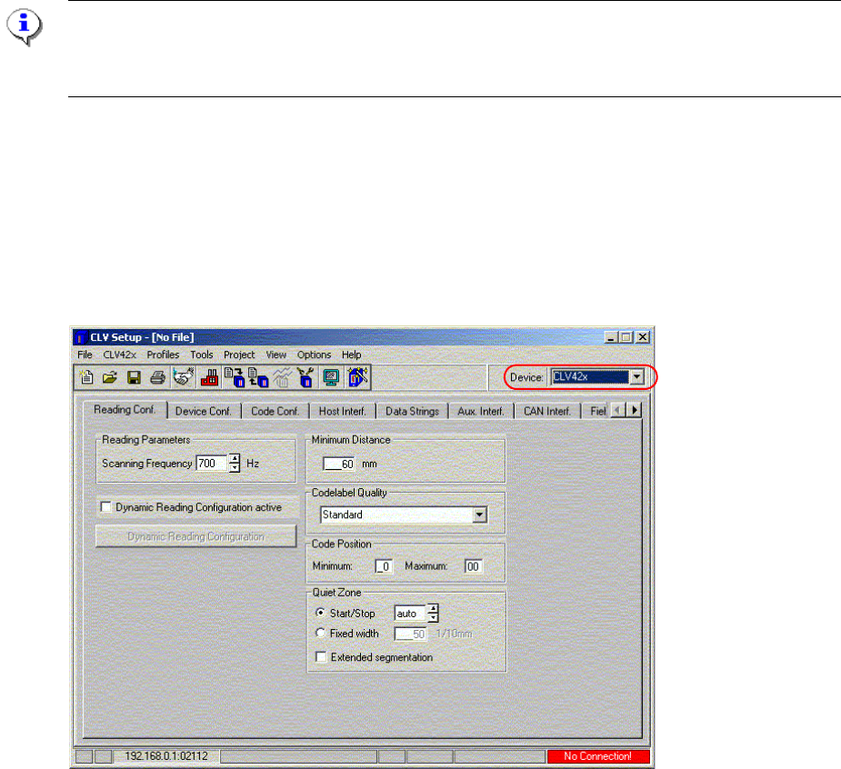
: Start the CLV program using Start--> Programs--> CLV Setup --> CL
V Setup V4.1 .
Fig. 2.11 - 8 Select the device type
: Select the barcode scanner type under Device.
: Leave all the settings in the ’Reading con
figuration’ window unchanged.
: Enter 1, 2, 3 or 4 in the 'Device no.' box in the
’Device configuration' window.
2 PCB barcode scanner assembly instructions SIPLACE
2.11 PCB barcode scanner configuration 10/2009 Edition
224
Convention for barcode scanner numbering:
Left-hand PCB conveyor track (2)
on dual conveyor option only
Right-hand PCB conveyor
track (1)
PCB
ba
rcode scanner ‘topside’
3 1
PCB barcode scanner
‘topside’
PCB co
nveyor
PCB barcode scanner
‘underside’
4 2
2
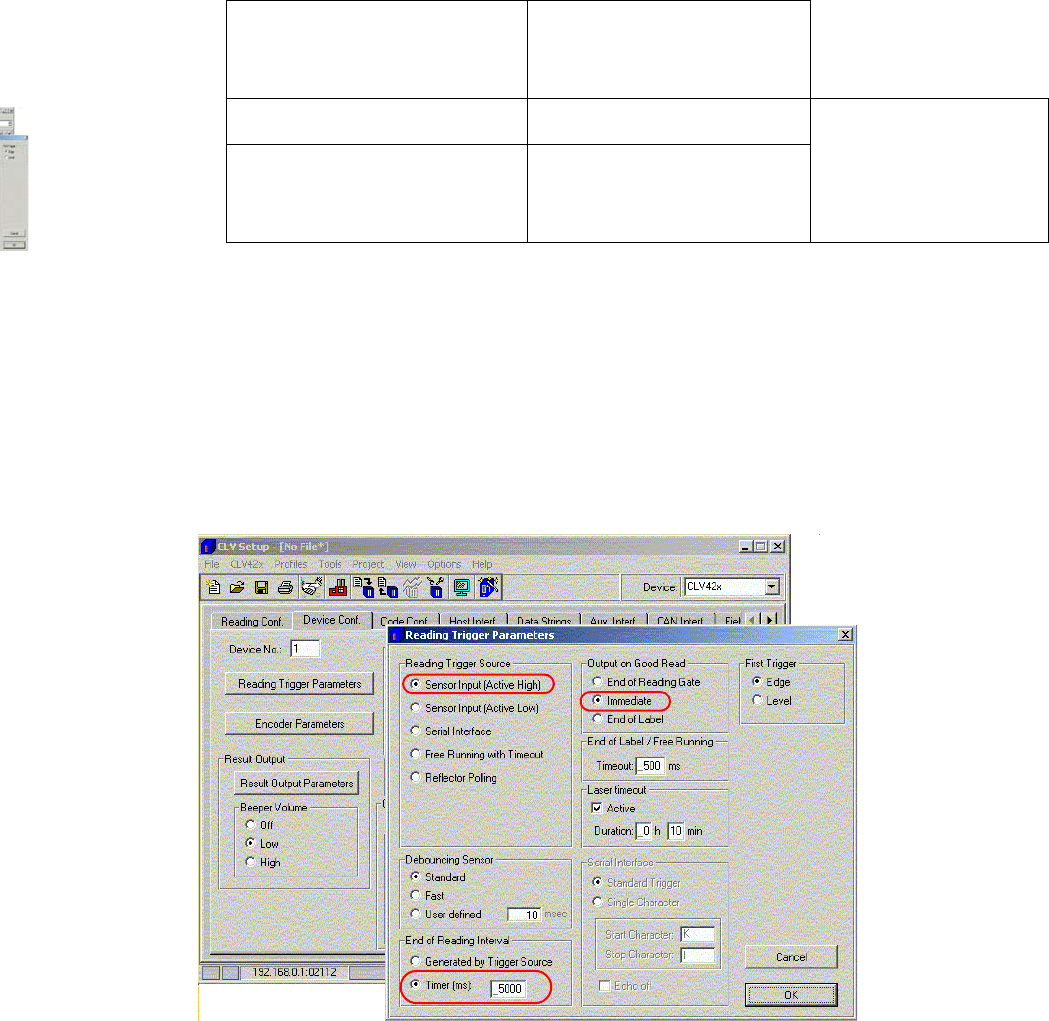
Fig. 2.11 - 9 ’Device configuration’
: Click on the ’Reading Trigger Parameters' button.
– In the ’Reading Trigger Source’ box, check the ’Sensor input (Active High)’ option
– In the ’Read clock end’ box, check the ’Timer (ms)
’
option and enter 5000 in the input box.
: In the ’Output on Good Read’ box, click on
the ’Immediate’ option.
: Click on OK to confirm your settings.
Fig. 2.11 - 10 "Reading Trigger Parameters" setting