00193891-0702_AI_LP_Barcode_DE+EN.pdf - 第250页
2 PCB barcode scanner assembly instructions SIPLACE 2.11 PCB barcode scanner configuration 10/2009 Edition 250 2.1 1.7.1 1 Completing the configuration: Once you have ente red all the det ails concerning the barcode, you…
SIPLACE 2 PCB barcode scanner assembly instructions
10/2009 Edition 2.11 PCB barcode scanner configuration
249
Input on the Data Strings tab --> Format Mask 2
– The format mask is used to define that only parts of a code are to be transferred. The number
of characters and the order in which they are transferred can be varied as required.
– The format mask contains up to 50 spaceholders. The spaceholder can specify the position of
the cod
ing to appear in the output string. Thus, if you enter "01 02 03", the first, second and
third characters of the coding will be transferred. Positions 01 to 90 may be entered.
– If the format mask is left blank, then
the entire code is sent.
– If a contiguous range, such as "02 -- 10" is entered in the mask, then the characters two to ten
of a co
de are transferred ("--" should be entered as 92). Up to three ranges may be defined.
– If "ZZ" is entered in the mask, the scanner transfer
s a "0" (zero) at the relevant point in the out-
put string. The "ZZ" character should be entered as 91.
Examples: For
mat mask = 01 02 03 12 13 Code string = 123456789abcd 2
==> Output = 123cd
Format mask = 01 -- 10 ZZ 20 -- 22 Code string = 123456789abcdefghijklmnopqrstuvwxyz
==> Output = 123456789a0klm
Filler: If
the spaceholder points to a point outside the code, then the scanner enters the
set filler cha
racter at this point. The default is "@" (40 hex). 2
2 PCB barcode scanner assembly instructions SIPLACE
2.11 PCB barcode scanner configuration 10/2009 Edition
250
2.11.7.11 Completing the configuration:
Once you have entered all the details concerning the barcode, you must then send the data to the
2D barcode scanner and test the barcode.
: Select the Download to device button (F4) to send the data.
Fig. 2.11 - 43 Download
: Save the configuration as a file using File --> Save File As.
2.11.7.12 Testing the configuration:
Once the configuration is complete, you can output an image of the defined barcode and make
any necessary changes to the contrast and focus.
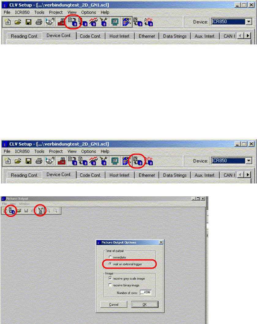
: Click on the "Picture Output" button to view
the scan result."
Fig. 2.11 - 44 Picture output
SIPLACE 2 PCB barcode scanner assembly instructions
10/2009 Edition 2.11 PCB barcode scanner configuration
251
: Select Options and activate the "Wait on external trigger" radio button..
: Enter the value 4096
in the "Number of rows" box.
: Click on OK to confirm your input and
select the "Receive image" button.
: Start Sitest --> PCB Conveyor Functions --> Functions
: Place a PCB with th
e configured 2D barcode on the input belt.
The barcode should be approx. 1 cm in front of the scanning beam.
: Click on the "Scan barcode with conveyor" button on
the Sitest user interface.
The PCB is transported and the barcode is scanned.
PLEASE NOTE:
A "Could not perform function" error message appears in SITEST.
Reason: The "Snap an image" function simply saves the image - no barcode information is read.
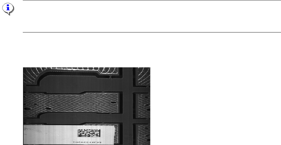
The following image should be output. If the image appears stretched, squashed or out-of-focus,
check the object velocity, focus height and contrast settings..
Fig. 2.11 - 45 Output image of the "DEMO" barcode
2
2
2
2
2
2
2
2