00193891-0702_AI_LP_Barcode_DE+EN.pdf - 第184页
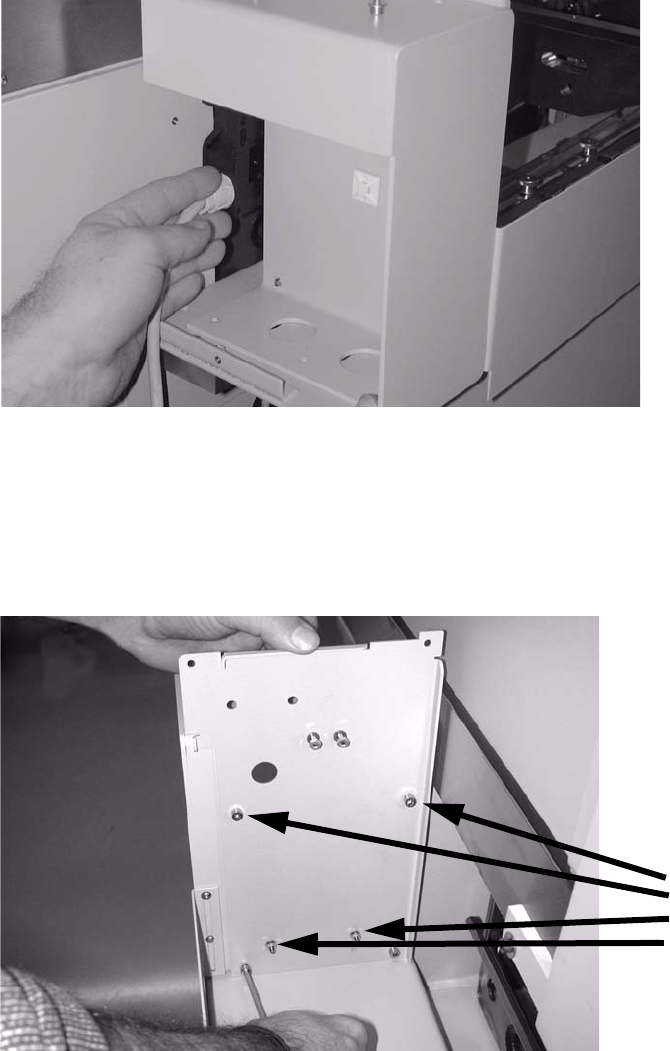
2 PCB barcode scanner assembly instructions SIPLACE 2.7 Installing the PCB barcode scanner 10/2009 Edition 184 : Pull the extension kit gently outwards and thre ad the cover switch cable through betwee n the machine and …
SIPLACE 2 PCB barcode scanner assembly instructions
10/2009 Edition 2.7 Installing the PCB barcode scanner
183
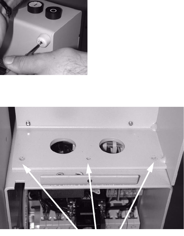
: Remove the rubber mounting.
2
2
: Loosen the three screws on the left side of the extension kit.
3 screws
2
2
2
2
2
2
2 PCB barcode scanner assembly instructions SIPLACE
2.7 Installing the PCB barcode scanner 10/2009 Edition
184
: Pull the extension kit gently outwards and thread the cover switch cable through between the
machine and the extension kit (see photo).
2
2
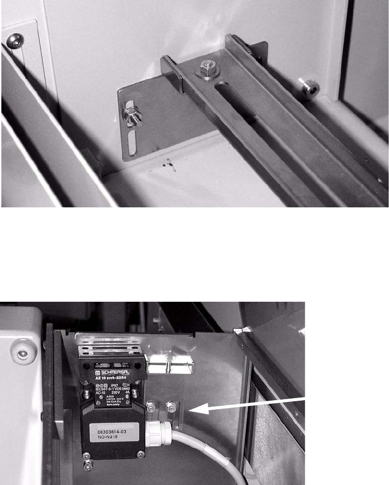
: Place the lower transverse rail in the extension kit.
: Screw the three screws up again.
: Screw the new s
idewalls into the PCB feeder with four screws (5 x 8).
4 screws
2
2
: Screw the cover switch on loosely.
The screw belongs in the through hole, not the slot.
SIPLACE 2 PCB barcode scanner assembly instructions
10/2009 Edition 2.7 Installing the PCB barcode scanner
185
: Fasten the supporting brackets for the bottom cross-rail.
: Place the ba
rcode scanner(s) in position.
: Insert the bottom c
ross-rail.
Adjust the position in the slot.
2
2
: Fit the top supporting bracket.
The screws go into the slots on the left as the cover switch has to be fastened to the left side
of the feed
er as well as the bracket.
Screws in left
slots
2
2
: Fit the top cross-rail. Adjust the position in the slot.
2