00193891-0702_AI_LP_Barcode_DE+EN.pdf - 第225页
SIPLACE 2 PCB barcode scanner assembly instructions 10/2009 Edition 2.11 PCB barcode scanner configuration 225 : Select the scan code in the ’Code con f.’ box. Fig. 2.1 1 - 1 1 Configure barcode types : Click on the barc…
2 PCB barcode scanner assembly instructions SIPLACE
2.11 PCB barcode scanner configuration 10/2009 Edition
224
Convention for barcode scanner numbering:
Left-hand PCB conveyor track (2)
on dual conveyor option only
Right-hand PCB conveyor
track (1)
PCB
ba
rcode scanner ‘topside’
3 1
PCB barcode scanner
‘topside’
PCB co
nveyor
PCB barcode scanner
‘underside’
4 2
2
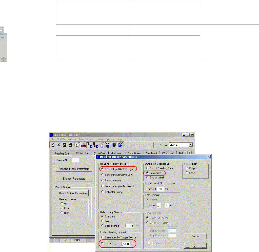
Fig. 2.11 - 9 ’Device configuration’
: Click on the ’Reading Trigger Parameters' button.
– In the ’Reading Trigger Source’ box, check the ’Sensor input (Active High)’ option
– In the ’Read clock end’ box, check the ’Timer (ms)
’
option and enter 5000 in the input box.
: In the ’Output on Good Read’ box, click on
the ’Immediate’ option.
: Click on OK to confirm your settings.
Fig. 2.11 - 10 "Reading Trigger Parameters" setting
SIPLACE 2 PCB barcode scanner assembly instructions
10/2009 Edition 2.11 PCB barcode scanner configuration
225
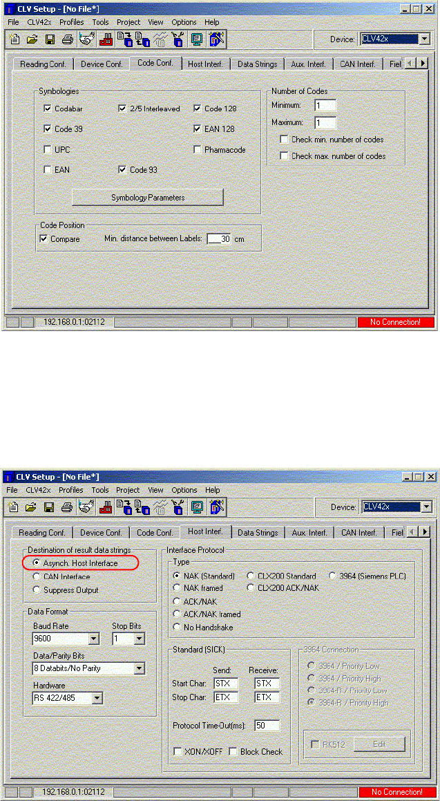
: Select the scan code in the ’Code conf.’ box.
Fig. 2.11 - 11 Configure barcode types
: Click on the barcode types to be read by the 1D barcode scanner.
: You can leave the settings in the ’Host Interface’ window
unchanged since you will not be es-
tablishing an online connection with the barcode scanner.
Fig. 2.11 - 12 Host interface
2 PCB barcode scanner assembly instructions SIPLACE
2.11 PCB barcode scanner configuration 10/2009 Edition
226
: Make sure that, under "Destination of result data strings" the 'Asynch. Host Interface' option is
selected so that the data will be analyzed and displayed by the station.
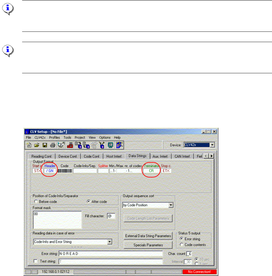
: Select the ’Data Strings’ window and enter the following values
-
in the ’Header’ box: /GN
- in the ’Terminator’ box: CR
Please note:
If the 1D or 2D barcode scanner is used on Siplace machines with p
latform 1 software, then a "CR"
must be entered for "Terminator".
NOTE:
Do not enter these values using the keyboard; simply click on
the ’Header’ box and the table will
appear.
: Enter the character / on the input line using the keyboard and click on GN.
: Click on O
K.
: Click on the ’Terminator’ box and accept the value CR from the table.
Fig. 2.11 - 13 Data string setting
: In the menu, click on the 'Profiles' pulldown menu.
: Select the 'Printer option' menu