00193891-0702_AI_LP_Barcode_DE+EN.pdf - 第251页
SIPLACE 2 PCB barcode scanner assembly instructions 10/2009 Edition 2.11 PCB barcode scanner configuration 251 : Select Options and activate the "W ait on external trigger" ra dio button.. : Enter the value 409…
2 PCB barcode scanner assembly instructions SIPLACE
2.11 PCB barcode scanner configuration 10/2009 Edition
250
2.11.7.11 Completing the configuration:
Once you have entered all the details concerning the barcode, you must then send the data to the
2D barcode scanner and test the barcode.
: Select the Download to device button (F4) to send the data.
Fig. 2.11 - 43 Download
: Save the configuration as a file using File --> Save File As.
2.11.7.12 Testing the configuration:
Once the configuration is complete, you can output an image of the defined barcode and make
any necessary changes to the contrast and focus.
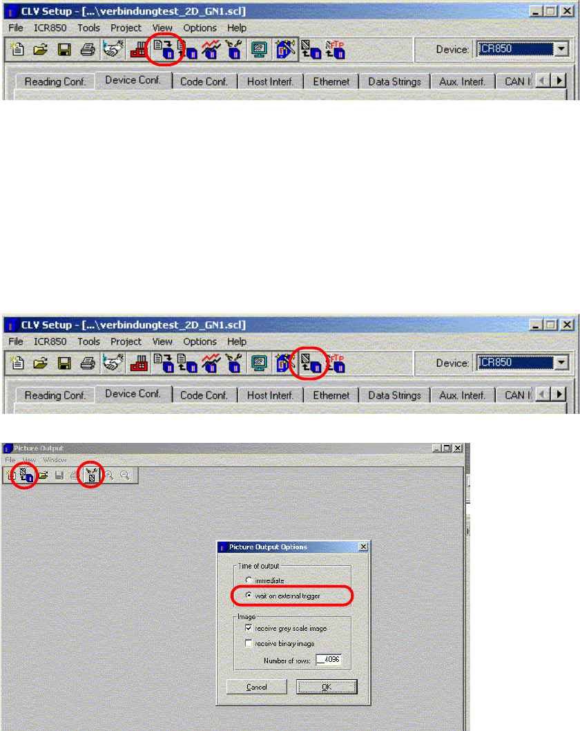
: Click on the "Picture Output" button to view
the scan result."
Fig. 2.11 - 44 Picture output
SIPLACE 2 PCB barcode scanner assembly instructions
10/2009 Edition 2.11 PCB barcode scanner configuration
251
: Select Options and activate the "Wait on external trigger" radio button..
: Enter the value 4096
in the "Number of rows" box.
: Click on OK to confirm your input and
select the "Receive image" button.
: Start Sitest --> PCB Conveyor Functions --> Functions
: Place a PCB with th
e configured 2D barcode on the input belt.
The barcode should be approx. 1 cm in front of the scanning beam.
: Click on the "Scan barcode with conveyor" button on
the Sitest user interface.
The PCB is transported and the barcode is scanned.
PLEASE NOTE:
A "Could not perform function" error message appears in SITEST.
Reason: The "Snap an image" function simply saves the image - no barcode information is read.
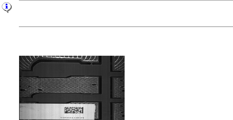
The following image should be output. If the image appears stretched, squashed or out-of-focus,
check the object velocity, focus height and contrast settings..
Fig. 2.11 - 45 Output image of the "DEMO" barcode
2
2
2
2
2
2
2
2
2 PCB barcode scanner assembly instructions SIPLACE
2.11 PCB barcode scanner configuration 10/2009 Edition
252
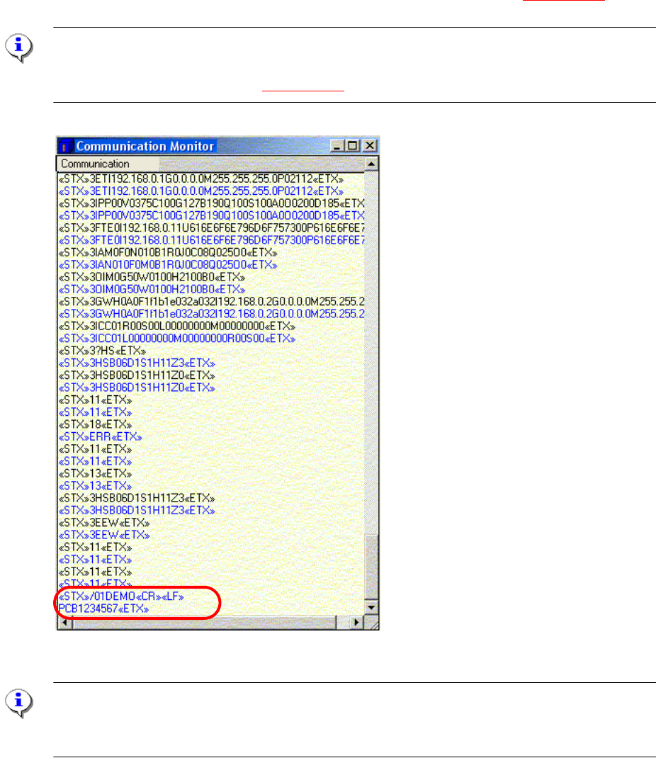
2.11.7.13 Communication Monitor
: Open the Communication Monitor from the View menu.
: On the "Host Interf
ace" tab, set the destination for the result string to Ethernet so that the scan-
ning result is displayed in the Communication Monitor.
The scanned barcode appears in clear text in the Communication Monitor (
Fig. 2.11 - 46).
PLEASE NOTE:
During the start-up phase, the "Ethernet" function can be activated in order to display the result in
the Communication Monitor (see Fig. 2.11 - 41)
Fig. 2.11 - 46 Communication Monitor with the scanned barcode
PLEASE Note:
When you close the Communication Monitor, the "Destination of
the result string" must be reset
to "Asynch. Host Interface" on the "Host Interface" tab.