00193891-0702_AI_LP_Barcode_DE+EN.pdf - 第161页
SIPLACE 2 PCB barcode scanner assembly instructions 10/2009 Edition 2.7 Installing the PCB barcode scanner 161 2.7.2 SIPLACE HS-50 / HS-60 / D4 / D1 / D2 2.7.2.1 Preparatory work : Switch the placement machine of f at th…

2 PCB barcode scanner assembly instructions SIPLACE
2.7 Installing the PCB barcode scanner 10/2009 Edition
160
: Set the distances between the 1D barcode scanner and the PCB so that the barcodes are read
reliably. This is achieved by moving the cross-rails up or down in the slots (see scanning field
diagram in
Chapter 2.11.4).
: Fo
r the 2D barcode scanner, set the distance to exactly 60 ± 1 mm.
Use the adjusting gauge provided
(see photograph on page 177).
The 2D scanner only works in this focus range.
2
The SICK software (version > 4.1) can be used to check the setting. 2
2
: Switch the placement machine on at the main switch.

SIPLACE 2 PCB barcode scanner assembly instructions
10/2009 Edition 2.7 Installing the PCB barcode scanner
161
2.7.2 SIPLACE HS-50 / HS-60 / D4 / D1 / D2
2.7.2.1 Preparatory work
: Switch the placement machine off at the main power switch.
2
HS-50 / HS-60 only: 2
: Check whether the fixing holes have been drilled for the PC
B barcode. If not, carry out the pre-
paratory work described in
Section 2.7.3.
2
For older HS-50 machines (version number < 800), the entire drilling pattern must be applied (see
Section 2.8). 2
For more recent HS-50 and older HS-60 machines, a thread must also be tapped (see drawing in
Section 2.8).
Do not use the HS-50 drilling gauge to do this. 2
: If drilling work is required, see the nex
t section, otherwise skip to the next section but one: Me-
chanical installation.
2 PCB barcode scanner assembly instructions SIPLACE
2.7 Installing the PCB barcode scanner 10/2009 Edition
162
2.7.3 Creating the fixing holes
Tools required 2
– Screw clamp 120 mm
– Power drill or cordless screwdriver
– Drill bit (3.3 mm)
–M4 tap
– ratchet tapper
– 2x M4x12 screw / HS-50
– Drilling gauge (item no.: 03026214-01) / HS-50.
2
2
Before starting to drill, cover all the electrical components in the extension kit in order to protect
them against drilling dust. 2
2
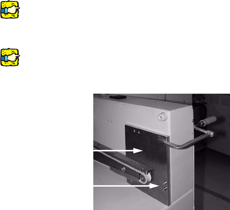
: Remove the hand guard on the extension kit.
: Fit the drilling gauge to the two threads for the hand
guard.
2
Make sure that the drilling gauge is seated on the base of the extension kit. 2
2
2
: Use the screw clamp to further secure the drilling gauge.
Drilling gauge
Fix drilling gauge using
these two screws.
2