00193891-0702_AI_LP_Barcode_DE+EN.pdf - 第257页
SIPLACE 2 PCB barcode scanner assembly instructions 10/2009 Edition 2.11 PCB barcode scanner configuration 257 7.General note s – The beam hit s the PCB at an angle of ap prox.15° from the vertical if the scanner is inst…
2 PCB barcode scanner assembly instructions SIPLACE
2.11 PCB barcode scanner configuration 10/2009 Edition
256
2.11.7.15 Possible sources of error
1. Problems establishing a connection
– Check the port ID and address
– Check cross-over cables
– With XP, deactivate and reactivate the network card (or reboot on an NT computer)
NOTE:
When you unplug the LAN cable, the connection on the CLV software remains "green".
When you plug in the LAN cable again, the connection must be established again.
Interface --> Options --> OK.
2.Problems snapping and assessing images
– The number of rows must be s
et to at least 4000
– Wait on external trigger
– The barcode to be read should be as close as possible to the beam
– Check the scanning distance if the image is fuzzy
3.Communication Monitor
– Host Interface: Set output to Ethernet. It is impo
rt
ant for production to reset it back to
Asynch. Host Interface.
– No result: Check the port ID or restart the program
– Quality assessment output
4.Barcode is not decoded
– Check the object velocity
– Check the cell size
5.Wrong or missing barcode in Sitest
– Enter /GN (enter again if you are in any do
ubt [se
lect from the list]) or check CR.
6.Auto Setup
– The barcode to be taught must be close to th
e scan
ning beam, as when snapping an image.
– The object velocity must b
e roughly correct
SIPLACE 2 PCB barcode scanner assembly instructions
10/2009 Edition 2.11 PCB barcode scanner configuration
257
7.General notes
– The beam hits the PCB at an angle of approx.15°
from the vertical if the scanner is installed
plane-parallel to the object surface. If the angle is less than 15°, the reflection is greater.
From around 5°, a total reflection occurs ==> And the barcode can no longer be read.
To minimize unwanted reflection
s, the barcode scanner should be fitted so that the scan-
ning beam hits at an angle of between 15° and 30°.
– The Sick programming software can be used to create an image of the barcode. This image
ca
n be used to assess whether the set speed is correct. If the speed set in the CLV software
is too fast, then the barcode will appear stretched on the image. If the speed is too slow,
then the barcode will appear squashed.
– With the recorded image, the minimu
m/maximum code position should be set as accurately
as possible to hide any unwanted structures (e.g.PCB conveyor side wall) and thus reduce
the analysis time of the barcode scanner.
– With Data Matrix code, the continuous delimiting line determines the size and angular po-
sition of the barcode. The opposite "black-white" pattern identifies the cell size and the num-
ber of cells. This edge area must not be disturbed or damaged. There must also be a "rest
zo
ne" one cell in size around the barcode. This zone must not contain any unwanted struc-
tures. (Otherwise the barcode position cannot be detected reliably).
There must only be one barcode in the template window (limit the template window) other-
wise you cannot be certain which barcode was found and decoded.
– Distribution board: Unwanted terminals (e.g. X2-
X4) must be bypassed by setting the
switch to ON.
2 PCB barcode scanner assembly instructions SIPLACE
2.12 Tips & tricks for the barcode scanner 10/2009 Edition
258
2.12 Tips & tricks for the barcode scanner
2.12.1 Background
This technical information was written because there are a few changes in the CLV_Setup soft-
ware version 4.3 compared to older versions. 2
We have also integrated new knowledge and practical experience gained in using the PCB bar-
code scanner. 2
This is simply a supplement to 00193891-05 Retr
ofit in
structions for PCB barcode scanner and
will shortly be incorporated into these retrofit instructions. 2
2.12.2 Software installation
The CLV software must be installed on the default path (C:\Program Files\SICK\CLV) as it is only
this path that is enabled to run the programs in the firewall. 2
If a firewall message appears on the desktop or if no image is displayed in the ImageFTP window,
then you
should check whether the install path specified above was actually used. 2
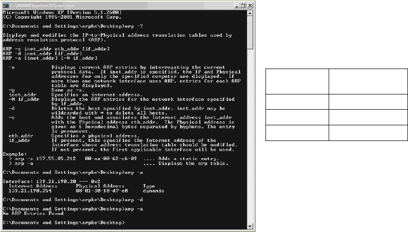
If you still cannot establish a connection to the scanner,
then you should delete the address res-
olution protocol (ARP). 2
To do this, select "Start" and then enter the command "cmd" to swit
ch to the DOS level (see picture
below). You can then use the following commands: 2
DOS
command
Description
arp -?
ARP / help
arp -a
ARP / display
arp -d
ARP / delete
2