80S-15贴片机.pdf - 第106页
4 Power S upply SIPLACE 80 S/F/G Service M anual Edition 04/97 4 - 10 4.2.3 Supply Voltages at Transformers and Rectifiers On the s ide o f the power suppl y uni t you wi ll find transforme rs T1 and T2, rectifi ers V1 -…
SIPLACE 80 S/F/G Service Manual 4 Power Supply
Edition 04/97
4 - 9
VorBox
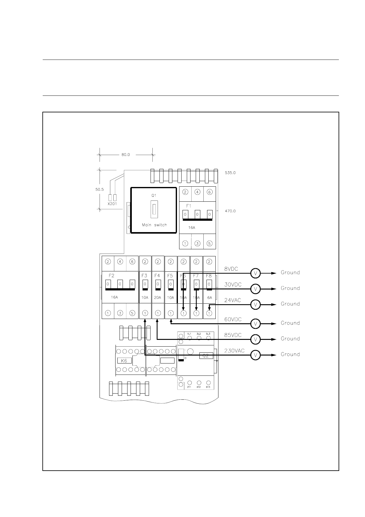
NOTE
When making detailed measurements or carrying out fault location in the power supply unit you should refer to
the relevant circuit diagram.
Fig. 4.2.2 Front view of power supply unit Y0952 (partial view) - measuring voltages

4 Power Supply SIPLACE 80 S/F/G Service Manual
Edition 04/97
4 - 10
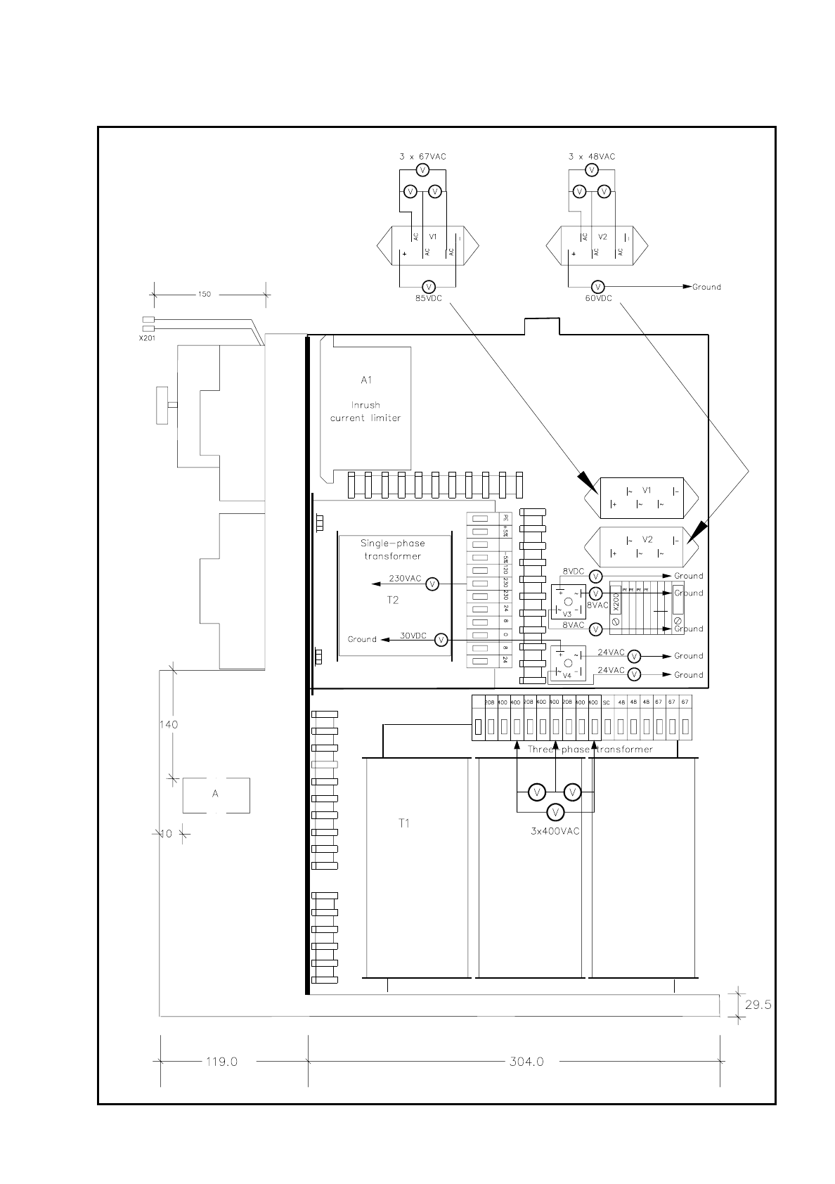
4.2.3 Supply Voltages at Transformers and Rectifiers
On the side of the power supply unit you will find transformers T1 and T2, rectifiers V1 - V4 and inrush current
limiter A1 (see Fig. 4.2.3).
NOTE
When making detailed measurements or carrying out fault location in the terminal rails or circuits you should
refer to the relevant circuit diagrams.
4.2.4 Overview of Voltage Supply Unit
Automatic circuit-breaker
or power circuit-breaker
Voltage Tripping current Circuit
F1 3 x 400 VAC 16 A Entire, after main switch
F2 3 x 400 VAC 16 A Transformer T1 with A1 via K1, K2
F3 1 x 230 VAC 10 A Transformer T2
F4 85 VDC not regulated 20 A 85 V after rectifier V1
F5 60 VDC not regulated 10 A 60 V after rectifier V2
F6 8 VDC not regulated 10 A 30 V after rectifier V3
F7 30 VDC not regulated 10 A 24 V after transformer T2
F8 24 VAC 6 A 24 V after transformer T2
Q1 3 x 400 VAC 0.24 - 0.4 A
Table 4.2 - 1 Overview of voltage supply unit
SIPLACE 80 S/F/G Service Manual 4 Power Supply
Edition 04/97
4 - 11
Fig. 4.2.3 Side view of power supply unit - transformers and rectifiers