80S-15贴片机.pdf - 第277页
SIPLACE 80S/F/G Service Manual 8 IC Head Edition 01/97 8 - 29 8.7 Disassemb le and Rea ssemble IC Head 8.7.1 To ols, Equipment 8.7.2 Spare Parts 8.7.3 Disassemble the IC Head ● Deta ch all pow er ca bles and ai r hos es.…
8 IC Head SIPLACE 80S/F/G Service Manual
Edition 01/97
8 - 28
8.6.5 Insert Nozzle into Nozzle Changer
●
Manually insert the new or serviced nozzles in the correct order into the nozzle changer.
●
Using the nozzle removal tool, turn each nozzle to the left in order to lock it in place in the nozzle changer.
●
Select the station menu functions Gantry 1
↵
Nozzle changer configuration to display the assignment and
check the desired and actual values of the assignment for consistency.
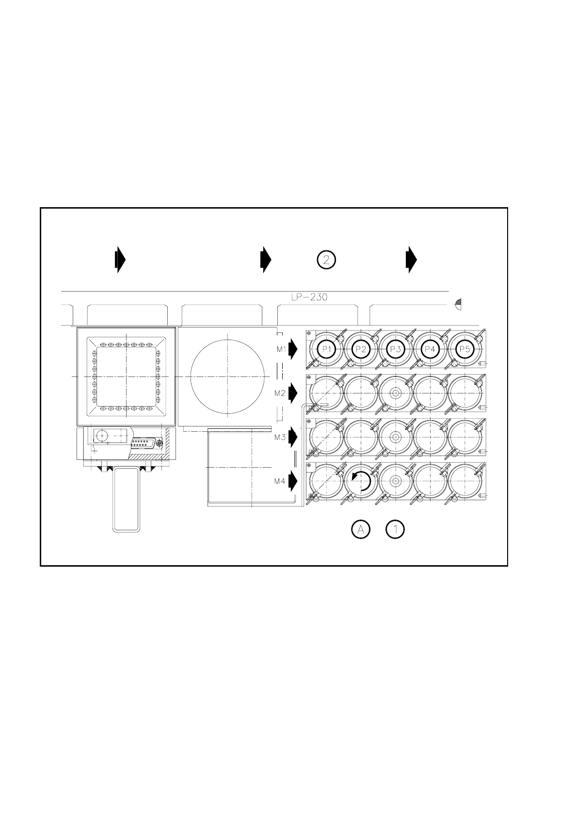
The general assignments are shown in the following diagram.
Fig. 8.6.1 Garage number of the nozzle changer
Key to Fig. 8.6.1
1 Nozzles 2 PCB transport direction
A Lock nozzle in place by turning to the left
SIPLACE 80S/F/G Service Manual 8 IC Head
Edition 01/97
8 - 29
8.7 Disassemble and Reassemble IC Head
8.7.1 Tools, Equipment
8.7.2 Spare Parts
8.7.3 Disassemble the IC Head
●
Detach all power cables and air hoses.
●
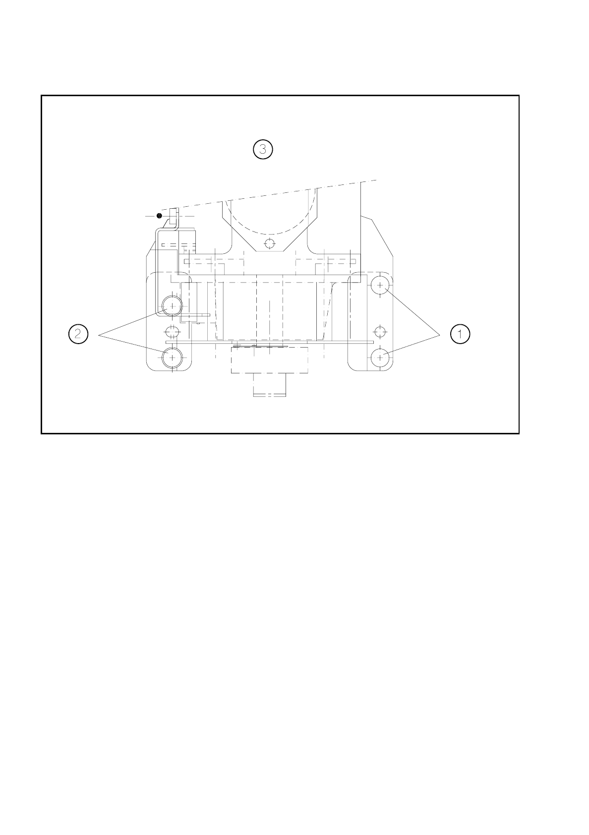
Loosen the four fixing screws for the IC head as shown in Fig. 8.7.1.
●
Remove the IC head and fix it to the mounting rack for the IC head.
8.7.4 Fit the IC Head
●
Fix the IC head in place using the 4 fixing screws. Please note that the screws are of different lengths! (see
Fig. 8.7.1 page 8 - 30)
●
Attach the power cables to the IC head board (see Fig. 8.2.2 page 8 - 8).
●
Reconnect the air hoses.
●
Edit the zero point correction values for the z and dr axes in the MA data.
●
Check the dynamic performance of the servo axes with reference to the Adjusting Instructions and adjust
the axes.
●
Measure the automatic placement machines with reference to the IC head.
From item number
Slotted head screw driver, set
Mounting rack for the IC head 00318295-01
SITEST program V
≥
203.000
Test box
Adjusting Instructions
From item number
IC head 00306366S02
8 IC Head SIPLACE 80S/F/G Service Manual
Edition 01/97
8 - 30
Fig. 8.7.1 Fixing screws for the IC head
Key to Fig. 8.7.1.
1 Fillister head screw M4 x 25 2 Fillister head screw M4 x 16
3 Viewed in the placement head mounting
direction