80S-15贴片机.pdf - 第371页
SIPLACE 80S/F/G Service Manual 9 Revolver Head Edition 04/97 9 - 87 9.9 Optical PCB Position Recognition (PCB Vision System) The opti cal PCB positio n recogn ition or the PCB v ision sys tem regi sters the exact positio…

9 Revolver Head SIPLACE 80S/F/G Service Manual
Edition 04/97
9 - 86
SIPLACE 80S/F/G Service Manual 9 Revolver Head
Edition 04/97
9 - 87
9.9 Optical PCB Position Recognition (PCB Vision
System)
The optical PCB position recognition or the PCB vision system registers the exact position of the PCB by
measuring the fiducials and then determines the offset in the x and y directions, the angle of rotation with
respect to the direction of PCB transportation and the shear of the PCB. Rejection markings (ink dots) are
also registered by the PCB vision system.
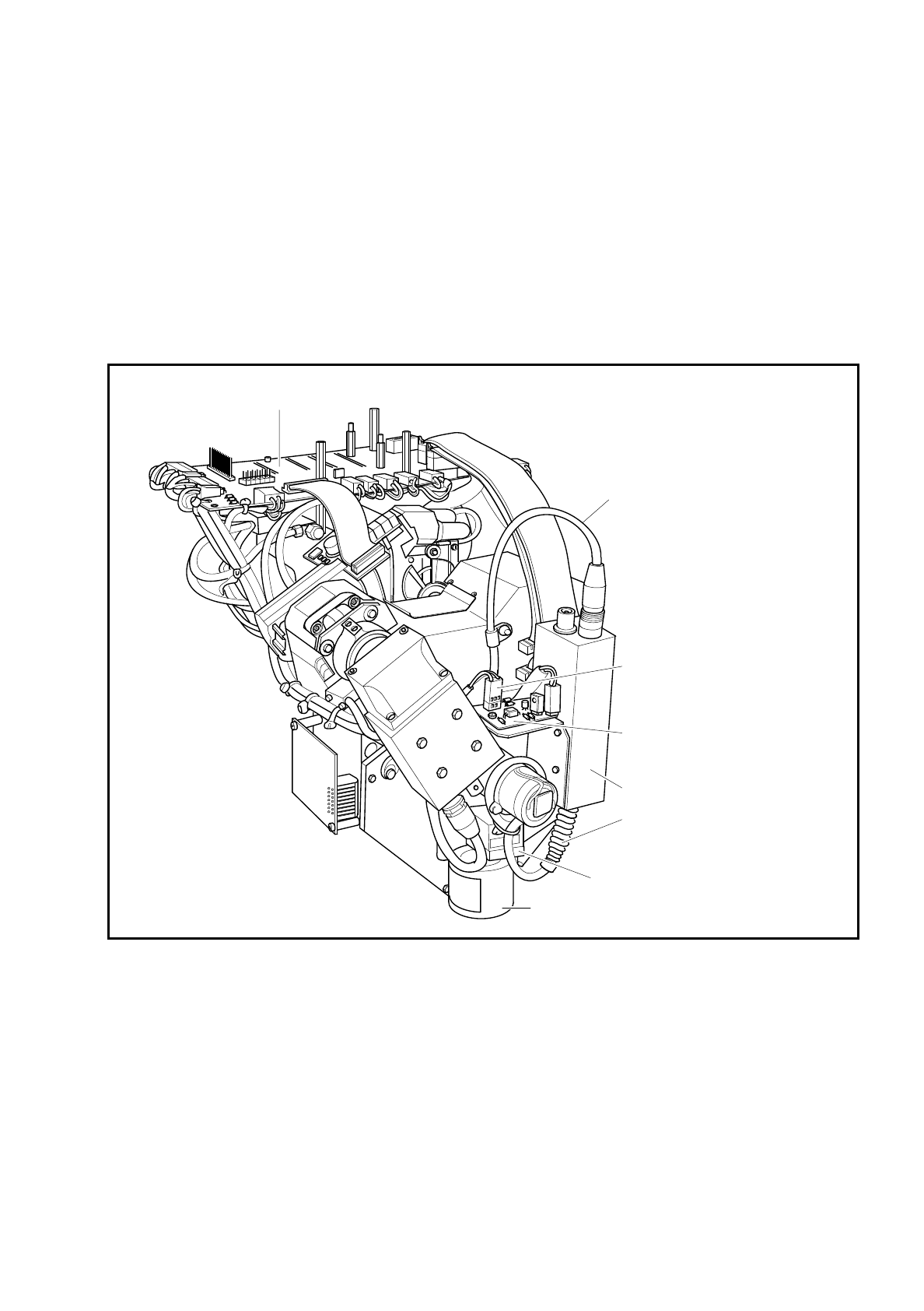
Fig. 9.9.1 Optical PCB position recognition (PCB board recognition)
Conversion board 'small axis' 1710460-Y0005
Y09597 cable to Y0005 conversion
board 'small axis' with power supply
for camera and signal lines to vision
evaluation unit MVS 100
Y0577-W1 cable to conversion
board 'small axis' Y0005
PCB optical system with illumination
Y0029 board
'illumination control PCB camera'
Camera amplifier Sony XC77
Cable CCD chip
camera amplifier
Housing with CCD chip

9 Revolver Head SIPLACE 80S/F/G Service Manual
Edition 04/97
9 - 88
9.9.1 System Description
The PCB position recognition system consists of
–
the optical system for PCB position recognition with
●
Sony XC77 a camera system with amplifier and CCD chip, field of view 5.7 mm x 5.7 mm
●
PCB lens with illumination
●
illumination controller board Y0029
–
the vision evaluation unit with
●
MVS100 motherboard with vision processor, interfaces and LED displays
●
MVS500 camera interface (piggyback board) for up to 4 CCD cameras.
9.9.2 Technical Data
Camera type: SONY XC77
Number of pixels: Camera 768 (H) x 493 (V)
image 640 (H) x 484 (V)
Pixel shape: rectangular
Field of view: 5.7 mm x 5.7 mm
Position measurement precision: ± 0.02 mm
Illumination method: incident light method (activated during measurement procedure)
Image processing: correlation principle, grey-scale system
Processor cycle time: < 200 msec
Screen: RGB monitor (VGA mode) 640 x 480 pixels on the station computer
Fiducials: library memory for up to 255 fiducial definition
9.9.3 Functional Description
Before placement the position, angle of rotation and shear of the PCB are determined by the PCB vision
system with the aid of the positions of the fiducials. Deviations from setpoint values will then be calculated into
the placement positions of the components.
At least 2 fiducials must have been applied to a PCB if the vision system is to detect deviations in the PCB
positioning and in the PCB angle of rotation. If 3 fiducials are applied to the board, you will also receive
information on compression and distortion of the PCB and of the board layout.
NOTE
Functional sequence, measuring procedure and selection of fiducials are described in the User's Manual
Section 7.2.