80S-15贴片机.pdf - 第373页
SIPLACE 80S/F/G Service Manual 9 Revolver Head Edition 04/97 9 - 89 9.10 Optical Compo nent Centering (Component Vision System) The opti cal com ponent ce ntering o r the com ponent vision system registe rs the pr ecise …

9 Revolver Head SIPLACE 80S/F/G Service Manual
Edition 04/97
9 - 88
9.9.1 System Description
The PCB position recognition system consists of
–
the optical system for PCB position recognition with
●
Sony XC77 a camera system with amplifier and CCD chip, field of view 5.7 mm x 5.7 mm
●
PCB lens with illumination
●
illumination controller board Y0029
–
the vision evaluation unit with
●
MVS100 motherboard with vision processor, interfaces and LED displays
●
MVS500 camera interface (piggyback board) for up to 4 CCD cameras.
9.9.2 Technical Data
Camera type: SONY XC77
Number of pixels: Camera 768 (H) x 493 (V)
image 640 (H) x 484 (V)
Pixel shape: rectangular
Field of view: 5.7 mm x 5.7 mm
Position measurement precision: ± 0.02 mm
Illumination method: incident light method (activated during measurement procedure)
Image processing: correlation principle, grey-scale system
Processor cycle time: < 200 msec
Screen: RGB monitor (VGA mode) 640 x 480 pixels on the station computer
Fiducials: library memory for up to 255 fiducial definition
9.9.3 Functional Description
Before placement the position, angle of rotation and shear of the PCB are determined by the PCB vision
system with the aid of the positions of the fiducials. Deviations from setpoint values will then be calculated into
the placement positions of the components.
At least 2 fiducials must have been applied to a PCB if the vision system is to detect deviations in the PCB
positioning and in the PCB angle of rotation. If 3 fiducials are applied to the board, you will also receive
information on compression and distortion of the PCB and of the board layout.
NOTE
Functional sequence, measuring procedure and selection of fiducials are described in the User's Manual
Section 7.2.

SIPLACE 80S/F/G Service Manual 9 Revolver Head
Edition 04/97
9 - 89
9.10 Optical Component Centering (Component Vision
System)
The optical component centering or the component vision system registers the precise position of a compo-
nent on the one hand by measuring the offset of component midpoint relative to the axis of symmetry of the
nozzle, and on the other hand, by measuring the rotational angle offset with respect to the relative rotational
position of the nozzle. It is also possible to analyze the state of the leads configuration in the x and y
directions.
9.10.1 System Description
The optical component centering system consists of
–
the optical System for position recognition of the components with
●
SONY XC75 camera with amplifier and CCD chip, deflector mirror, field of view 18 mm x 18 mm
●
component lens with LED illumination at different levels
●
illumination controller board Y0059
–
the vision evaluation unit with
●
MVS 100 motherboard with vision processor, interfaces and LED display
●
MVS 500 camera interface (piggyback board) for up to 4 CCD cameras
9.10.2 Technical Data
Camera type: SONY XC75
Number of pixels: Camera 768 (H) x 493 (V)
Image 640 (H) x 484 (V)
Pixel shape: rectangular
Field of view: 18 x 18 mm
2
Precision of positioning measurement: ± 0.02 mm
Precision of angular measurement: < 0.2 ° (depends on component)
Illumination method: Incident light method (red light)
Image processing: HALE grey-scale technique (High Accuracy Lead Extraction)
Evaluation time with lead test: approx. 230 msec (PLCC18)
approx. 140 msec with small components
Screen: RGB monitor (VGA mode) 640 x 480 pixels
Component sizes: 1 x 0.5 mm
2
... 14 x 14 mm
2
Range of recognized components: TSOP, LCC, PLCC, QFP, SO series, etc.
basically all components with
J and gullwing leads
Minimum lead spacing: 0.5 mm
Measurement precision per lead: 0.04 mm (or better)
Number of package forms:
≤
2047
9 Revolver Head SIPLACE 80S/F/G Service Manual
Edition 04/97
9 - 90
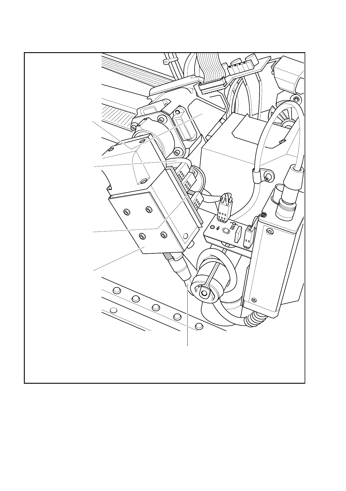
Fig. 9.10.1 Optical component centering (component vision system)
Optical component
centering unit with
illumination
Cable Y0575-W1
to conversion board
'small axis' Y0005
Y0059 board
Component illumination
control (older version
Y0028)
Camera amplifier
Sony XC75
Camera cable Y0574-W1 for power supply and signal lines
to conversion board 'small axis' Y0005