80S-15贴片机.pdf - 第134页
5 Gantries SIPLACE 80 S/F/G Service M anual Edition 04/97 5 - 16
SIPLACE 80 S/F/G Service Manual 5 Gantries
Edition 04/97
5 - 15
5.4.3 Installation
●
Fit the new motor using the mounting screws.
●
Restore the motor’s electrical connections (depending on the gantry)
NOTE
Route your cables with care.
●
Tension the cut toothed belt as described in Table 5.4 - 1.
●
Fit the components table support and the sliding plate holder.
●
Replace the empty tape cutter and restore all electrical and pneumatic connections.
●
Carry out a complete adjustment of the y axis (see adjustment instructions).
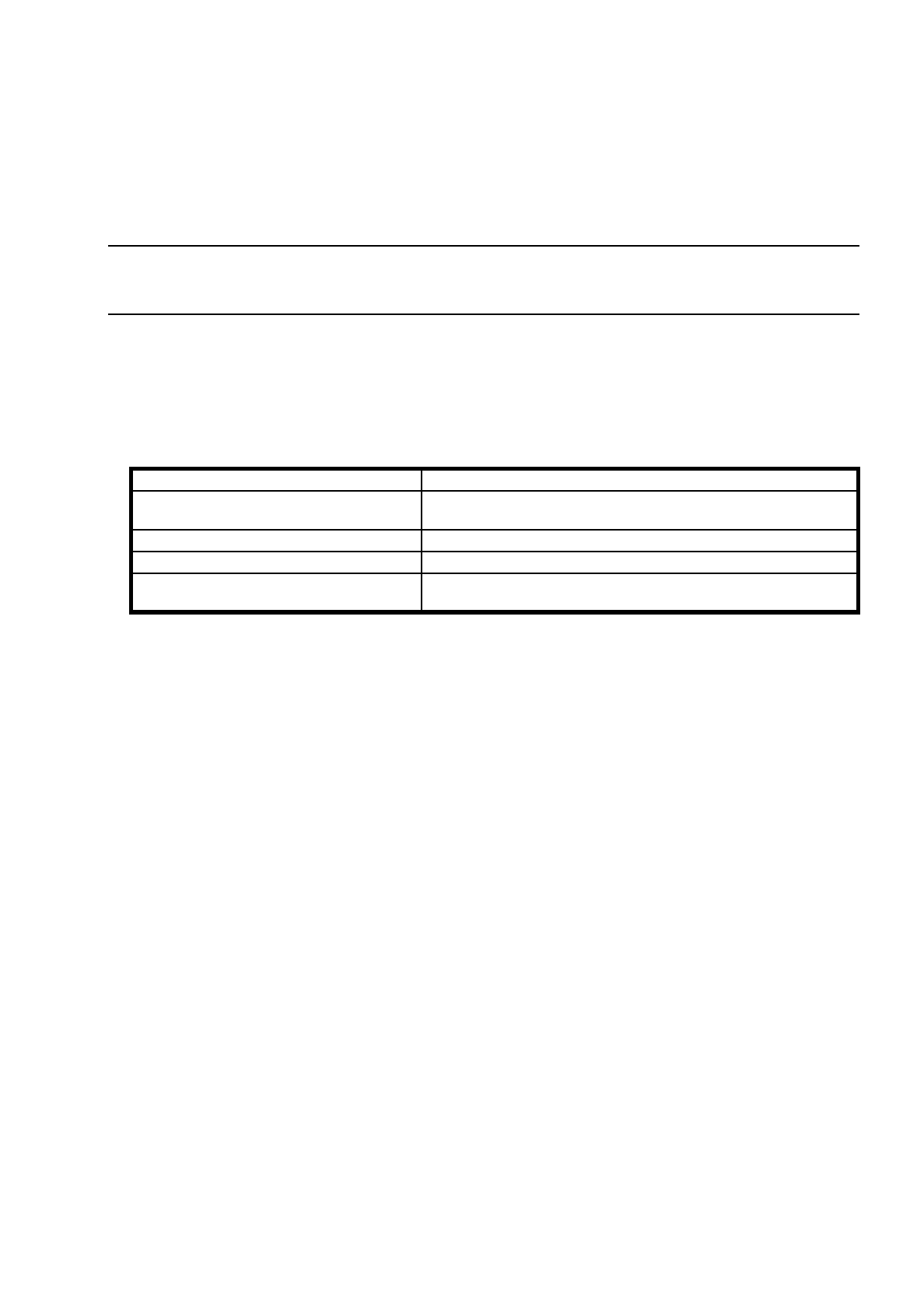
Key to Fig. 5.4.1.
Toothed belt 50AT5/2795-M
Measurement length of the toothed belt
600 mm from the center of the motor pinion to the center of the ten-
sioning pulley of the turnbuckle
Measurement position Middle of the toothed belt (300 mm)
Frequency of the new toothed belt 52 Hz ± 1 Hz
Frequency of the toothed belt once run in
(t
≥
5 hours
)
49 Hz ± 1 Hz
Table 5.4 - 1 Required adjustment of the cut toothed belt for the y axis
1 Deflection pulley 2 Turnbuckle
3 Cut toothed belt 4 Motor pinion of Y drive motor
5 Mounting screw (hexagon socket) 6 600 mm distance for adjustment of toothed belt tension

5 Gantries SIPLACE 80 S/F/G Service Manual
Edition 04/97
5 - 16

SIPLACE 80S/F/G Service Manual 6 PCB Handling
Edition 01/96
6 - I
Contents
Page
6 PCB Handling
6.1 Introduction. . . . . . . . . . . . . . . . . . . . . . . . . . . . . . . . . . . . . . . . . . . . . . . . . . . . . . . . . . . . . . 6 - 3
6.1.1 Safety Instructions . . . . . . . . . . . . . . . . . . . . . . . . . . . . . . . . . . . . . . . . . . . . . . . . . . . . . . . . .6 - 3
6.1.2 Tools, Auxiliary Materials and Equipment Required. . . . . . . . . . . . . . . . . . . . . . . . . . . . . . . . 6 - 3
6.1.3 Overview of Functions . . . . . . . . . . . . . . . . . . . . . . . . . . . . . . . . . . . . . . . . . . . . . . . . . . . . . . 6 - 3
6.1.4 Position of the Assemblies (General Views). . . . . . . . . . . . . . . . . . . . . . . . . . . . . . . . . . . . . .6 - 4
6.2 Geared Motors of the PCB Transportation Systems. . . . . . . . . . . . . . . . . . . . . . . . . . . . . 6 - 7
6.2.1 Replacing the input and center conveyor geared motors. . . . . . . . . . . . . . . . . . . . . . . . . . . . 6 - 7
6.2.1.1 Removing the geared motor from the input and output conveyors. . . . . . . . . . . . . . . . . . . . . 6 - 7
6.2.1.2 Fitting and testing the input and center conveyor geared motors. . . . . . . . . . . . . . . . . . . . . . 6 - 9
6.2.2 Replacing the output conveyor geared motor. . . . . . . . . . . . . . . . . . . . . . . . . . . . . . . . . . . . . 6 - 9
6.2.2.1 Removing the geared motor from the output conveyor . . . . . . . . . . . . . . . . . . . . . . . . . . . . . 6 - 9
6.2.2.2 Fitting and testing the output conveyor geared motor . . . . . . . . . . . . . . . . . . . . . . . . . . . . . 6 - 11
6.3 Drive Units of the PCB Transportation Systems. . . . . . . . . . . . . . . . . . . . . . . . . . . . . . . 6 - 13
6.3.1 Replacing the drive unit of the input conveyor . . . . . . . . . . . . . . . . . . . . . . . . . . . . . . . . . . . 6 - 13
6.3.1.1 Removing the input or output conveyor drive units . . . . . . . . . . . . . . . . . . . . . . . . . . . . . . . 6 - 13
6.3.1.2 Fitting and testing the input and output conveyor drive units . . . . . . . . . . . . . . . . . . . . . . . . 6 - 15
6.3.2 Replacing the drive unit of the center conveyor . . . . . . . . . . . . . . . . . . . . . . . . . . . . . . . . . . 6 - 16
6.3.2.1 Removing the center conveyor drive unit. . . . . . . . . . . . . . . . . . . . . . . . . . . . . . . . . . . . . . .6 - 16
6.3.2.2 Fitting the center conveyor drive unit . . . . . . . . . . . . . . . . . . . . . . . . . . . . . . . . . . . . . . . . . .6 - 16
6.3.3 Replacing the output conveyor drive unit . . . . . . . . . . . . . . . . . . . . . . . . . . . . . . . . . . . . . . . 6 - 18
6.3.3.1 Removing and installing the output conveyor drive unit. . . . . . . . . . . . . . . . . . . . . . . . . . . . 6 - 18
6.4 Conveyor Toothed Belts . . . . . . . . . . . . . . . . . . . . . . . . . . . . . . . . . . . . . . . . . . . . . . . . . . 6 - 19
6.4.1 Replacing the conveyor toothed belt on the fixed side of the board conveyor. . . . . . . . . . . 6 - 19
6.4.1.1 Changing the conveyor toothed belt on the fixed side of the board conveyor . . . . . . . . . . . 6 - 19
6.4.1.2 Function Test . . . . . . . . . . . . . . . . . . . . . . . . . . . . . . . . . . . . . . . . . . . . . . . . . . . . . . . . . . . .6 - 21
6.4.2 Replacing the conveyor toothed belt on the movable side of the board conveyor. . . . . . . . 6 - 21
6.4.2.1 Changing the conveyor toothed belt on the movable side of the board conveyor . . . . . . . . 6 - 21
6.4.2.2 Function Test . . . . . . . . . . . . . . . . . . . . . . . . . . . . . . . . . . . . . . . . . . . . . . . . . . . . . . . . . . . .6 - 23
6.5 Retainers and Compression Springs . . . . . . . . . . . . . . . . . . . . . . . . . . . . . . . . . . . . . . . . 6 - 25
6.5.1 Removing retainers and compression springs . . . . . . . . . . . . . . . . . . . . . . . . . . . . . . . . . . . 6 - 25
6.5.2 Fitting the retainers and compression springs . . . . . . . . . . . . . . . . . . . . . . . . . . . . . . . . . . .6 - 27
6.5.3 Function test. . . . . . . . . . . . . . . . . . . . . . . . . . . . . . . . . . . . . . . . . . . . . . . . . . . . . . . . . . . . . 6 - 27
6.6 Aligning the Guide Rails . . . . . . . . . . . . . . . . . . . . . . . . . . . . . . . . . . . . . . . . . . . . . . . . . . 6 - 29