80S-15贴片机.pdf - 第420页
9 Revolver Head SIPLACE 80S/F/G Service Manual Edition 04/97 9 - 136 9.18.4 Replacing the stop ● Loose n the two M1.6 x 8 counte rsunk sc rews for fixi ng the cove r plate (see item 2a in Fig. 9.18.1) and st op (see it e…
SIPLACE 80S/F/G Service Manual 9 Revolver Head
Edition 04/97
9 - 135
●
Insert the new DC motor and fix in place.
●
Push new heat-shrink sleeves over the motor cable.
●
Solder the cable to the DC motor. Check that the polarity of the terminals is correct:
Cable colors: red = +, black =
−
●
Carefully shrink on the heat-shrink sleeves using the hot air gun.
●
Lightly grease the teeth of toothed wheel 1 with Unimoly GL82.
●
Fix toothed wheel 1 in place.
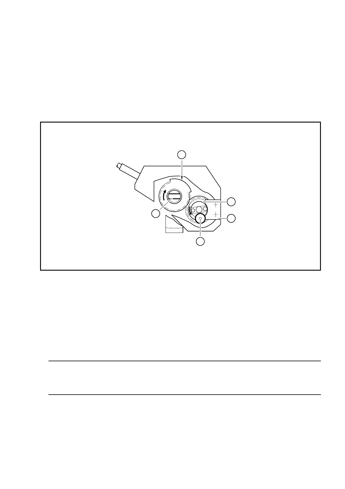
Check the position of the screwdriver blade with respect to toothed wheel 1 against the following diagram:
Fig. 9.18.2 Position of toothed wheel 1 and the screwdriver blade during reassembly
Key to Fig. 9.18.2
●
Fix the stop with the cover plate
PLEASE NOTE:
After assembly, the star can only turn the segments if the head was assembled while the screwdriver
blade was in the horizontal position (see item 2 in Fig. 9.18.2).
●
Check the functioning of screwdriver 1 with reference to the adjustment instructions and using the SITEST
program.
1Stop
2 Toothed wheel 1
3 The BERO trigger surface is in the top position
4 The screwdriver blade is horizontal
5 The small stop wheel of toothed wheel 1 is against the stop
3
2
1
5
4

9 Revolver Head SIPLACE 80S/F/G Service Manual
Edition 04/97
9 - 136
9.18.4 Replacing the stop
●
Loosen the two M1.6 x 8 countersunk screws for fixing the cover plate (see item 2a in Fig. 9.18.1) and stop
(see item 2 in Fig. 9.18.1).
●
Reverse the above sequence to install.
PLEASE NOTE:
After assembly, the star can only turn the segments if the head was assembled while the screwdriver
blade was in the horizontal position (see item 2 in Fig. 9.18.2).
●
Check the functioning of screwdriver 1 with reference to the adjustment instructions and using the SITEST
program.
9.18.5 Replacing toothed wheel 1
Dismantling and assembly of toothed wheel 1 are described in Section 9.18.3 on page 9 - 133. When assem-
bling the toothed wheel, pay particular attention to the position of the screwdriver blade with respect to the
toothed wheel, as shown in Fig. 9.18.2 on page 9 - 135.
9.18.6 Replacing the BERO
●
Loosen the M 1.6 x 4 fillister head screws for fixing the cable brackets (see item 4 in Fig. 9.18.3).
●
Loosen the M 1.6 x 4 fillister head screws (see item 2 in Fig. 9.18.3) for clamping the BERO (see item 1 in
Fig. 9.18.3).
●
Cut the connecting cable to the BERO and pull the BERO out of the hole.
●
Remove the board cover (see item 5 in Fig. 9.18.3).
●
Unsolder the connecting cable from the BERO to the conversion board Y0307 (see items 1, 2 and 3 in Fig.
9.18.4).
CAUTION
OO
Do NOT dismantle the lifting carriage when you replace the cable. Otherwise you will have to return the
head to the factory to be reset.
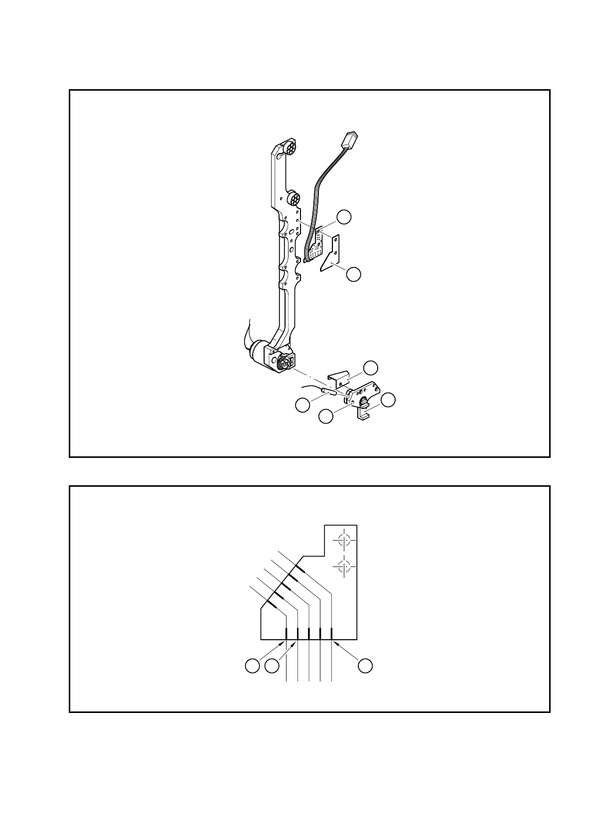
Key to Fig. 9.18.3
1 BERO
2 M 1.6 x 4 fillister head screws for clamping the BERO
3 Segment claw
4 Cable bracket
5 Board cover
6 ’Screwdriver 1’ conversion board Y0307
SIPLACE 80S/F/G Service Manual 9 Revolver Head
Edition 04/97
9 - 137
Fig. 9.18.3 BERO of screwdriver 1
Fig. 9.18.4 Wiring diagram for the ’Screwdriver 1’ BERO on conversion board Y0307
Key to Fig. 9.18.4
1 + 24 V: brown
2 GND 24 V: blue
3 BERO signal: black
5
6
4
2
1
3
3
1 2