80S-15贴片机.pdf - 第367页
SIPLACE 80S/F/G Service Manual 9 Revolver Head Edition 04/97 9 - 83 – Sleeve compl ete, c onsisti ng of ● Preas sembled slee ve wit h nozz le seati ng for Ve rsion 1 nozz les ● Scale disk ( incrementa l disk ) for det er…
9 Revolver Head SIPLACE 80S/F/G Service Manual
Edition 04/97
9 - 82
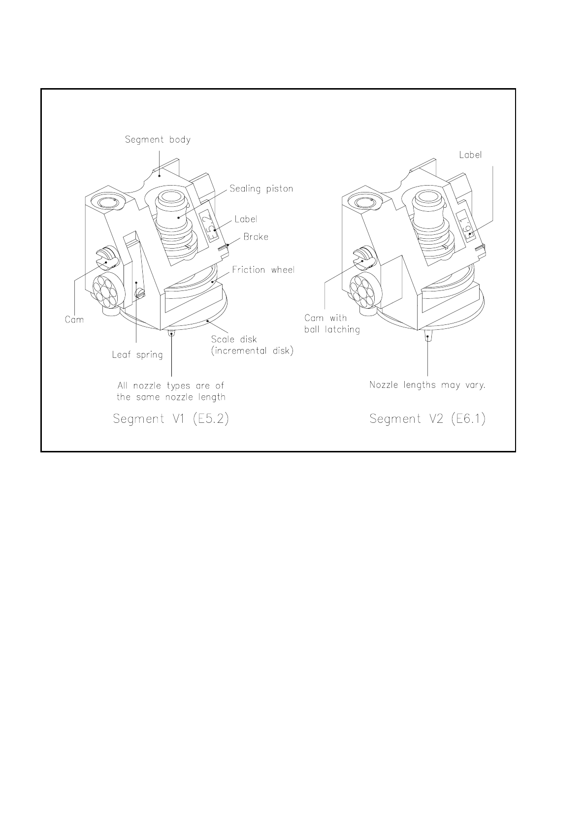
Fig. 9.8.2 Segments V1 and V2
9.8.2 Structure and Functioning of Segment Version 1
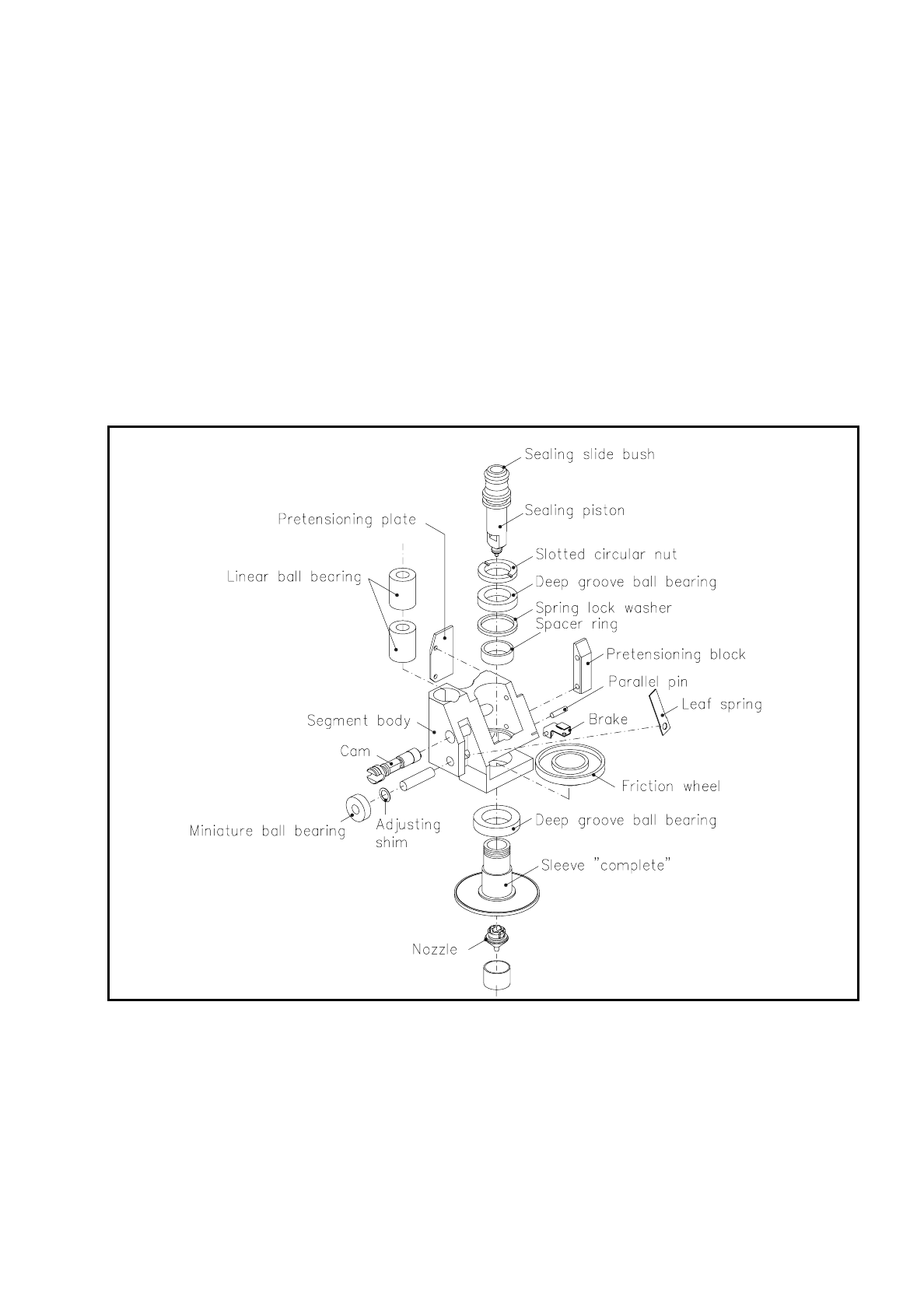
Fig. 9.8.3 shows in exploded view the components of the Version 1 segment. It basically consists of the
following components:
–
Segment body
–
2 linear ball bearings for guiding the segment along the guide shaft of the revolver head
–
Sealing piston Version 1 with bronze bush as sealing slide bush. The bronze bush slides along the vacuum
tube of the revolver head and seals off the vacuum duct.
–
Pretensioning block, pretensioning plate for guidance along the revolver head web, and pin for lifting the
ball cage when the lifting slide raises the segment from the lower position in revolver head station 1 into
the upper position so that the revolver head can cycle on.
–
Miniature ball bearing
During the rotational movement of the revolver head this bearing slides along the arc guides. In revolver
head stations 1 and 7 the arc guides are not continuous - that is, they have gaps:
●
In revolver head station 7 the segments can be installed or removed.
●
In revolver head station 1 the miniature ball bearing slides into the segment claw of the lifting slide
where it is lowered for picking-up and inserting components and then raised back into the top position
in order to cycle on the revolver head.
SIPLACE 80S/F/G Service Manual 9 Revolver Head
Edition 04/97
9 - 83
–
Sleeve complete, consisting of
●
Preassembled sleeve with nozzle seating for Version 1 nozzles
●
Scale disk (incremental disk) for determination of the rotational angle and zero pulse at turning
stations dp1 and dp2
●
Protective ring and anti-dazzle foil for the scale disk
–
Lower deep-grooved ball bearing, friction wheel, spacer ring, spring lock washer and top deep-grooved
ball bearing are slid onto the sleeve and fixed in place with the slotted nut.
The feed motor of the turning station swings the turning station up to the segment, until the drive o-ring
touches the friction wheel of the segment. The o-ring transmits the rotational movement of the drive motor
onto the friction wheel and thus onto the sleeve with nozzle.
Fig. 9.8.3 Design of segment version 1
9 Revolver Head SIPLACE 80S/F/G Service Manual
Edition 04/97
9 - 84
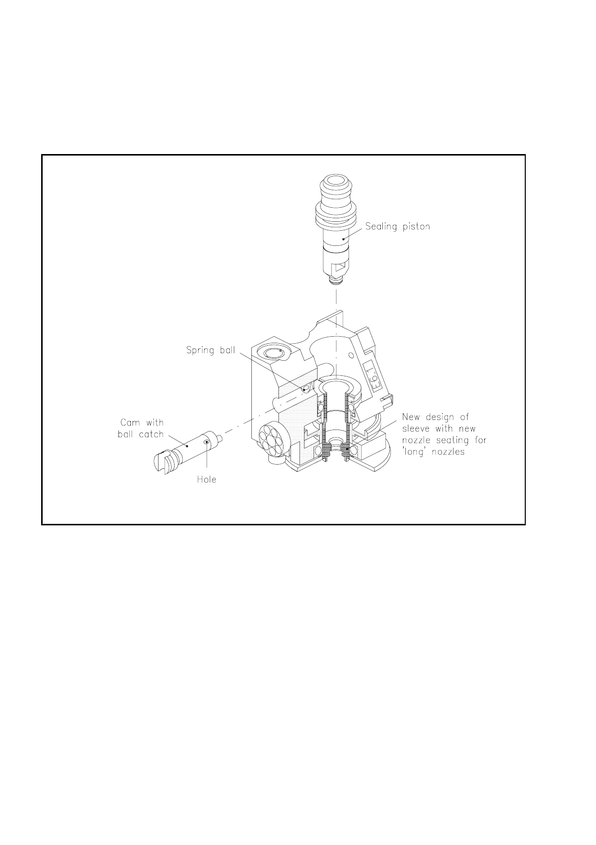
9.8.3 Structure and Functioning of Segment Version 2
Fig. 9.8.4 shows in sectional view the components of the version 2 segment.
Fig. 9.8.4 Design of segment version 2
The version 2 segment has basically the same structure and the same functions as the version 1 segment.
Some components are however different. These include:
–
The cam
The cam is no longer held in its end positions by the spring plate. A spring ball is let into the segment body.
The ball then latches into the hole of each end position of the cam and thus holds it in that position.
–
The sleeve
The sleeve has a new design of nozzle seating. It takes the new generation of nozzles which is
characterized by the following features:
●
The placement shadow is considerably reduced.
●
Components as tall as 6 mm can now be inserted.
●
The reliability and sealing of the nozzle seating has been improved.
●
The nozzle removal force is reproducible.