80S-15贴片机.pdf - 第465页
10 Si plac e G au tom atic g lue ap plic ator SIPLA CE 80 S/80 F/G Servi ce Ma nua l Ed itio n 06 /98 10 - 56 Checking the offset See "Adj ust ing the offs et". Reset the MA data to basic data (see T able 10.3.…
10 Siplace G automatic glue applicator SIPLACE 80S/80F/G Service Manual
Edition 06/98
10 - 52
Fig. 10.3.14 Speed and P gain for the X2 axis (P gain too high)
10.3.6.5 X axis
General preparatory work
● The gluing heads and cameras must be fitted in order to set the axes.
● Use an RC filter to record the current curve and the diagnostic strip test point signal.
● Carry out a head reference sequence and an x reference sequence.
● Switch the machine on for approximately 30 minutes.
Setting the offset
Preparation:
● Connect an axis test box to the axis board and set the position display to axis number 0.
● Change the MA data for offset adjustment and reference the axis (see Table 10.3.1).
● Position the X axis at 200,000.
Setting:
● Use the offset potentiometer on the servo board to set the axis position to 200,000 ± 1 digit.
Check:
● The axis position display should not deviate from the value of 200,000 by more than 1 digit.
Vnom value
MP6 current curve of servo board
Positional deviation
End signal
P gain too high.
Current oscillating
If distance: 000000-002800
V: 10 accel.: 100 decel.: 50
SIPLACE 80S/80F/G Service Manual 10 Siplace G automatic glue applicator
Edition 06/98
10 - 53
Setting the speed (see Fig. 10.3.15)
Preparation:
● Change the MA data for adjusting the speed and then reference the axis (see Table 10.3.2)
● Connect an axis test box to the axis board and set to time measurement - axis 0.
● Set the axis to continuous operation for a distance of 100,000 - 300,000 digits.
Setting:
● Increase the P gain on the servo board until the axis can be easily positioned.
● Use the tacho potentiometer on the X servo board to set the f/V converter signal at the diagn. strip
to the zero line ± 500 mV once the speed is reached (max. setpoint values) (see Fig. 10.3.15).
Check:
● The positioning time must be 980ms ±15ms (time measured with a suitable P gain)
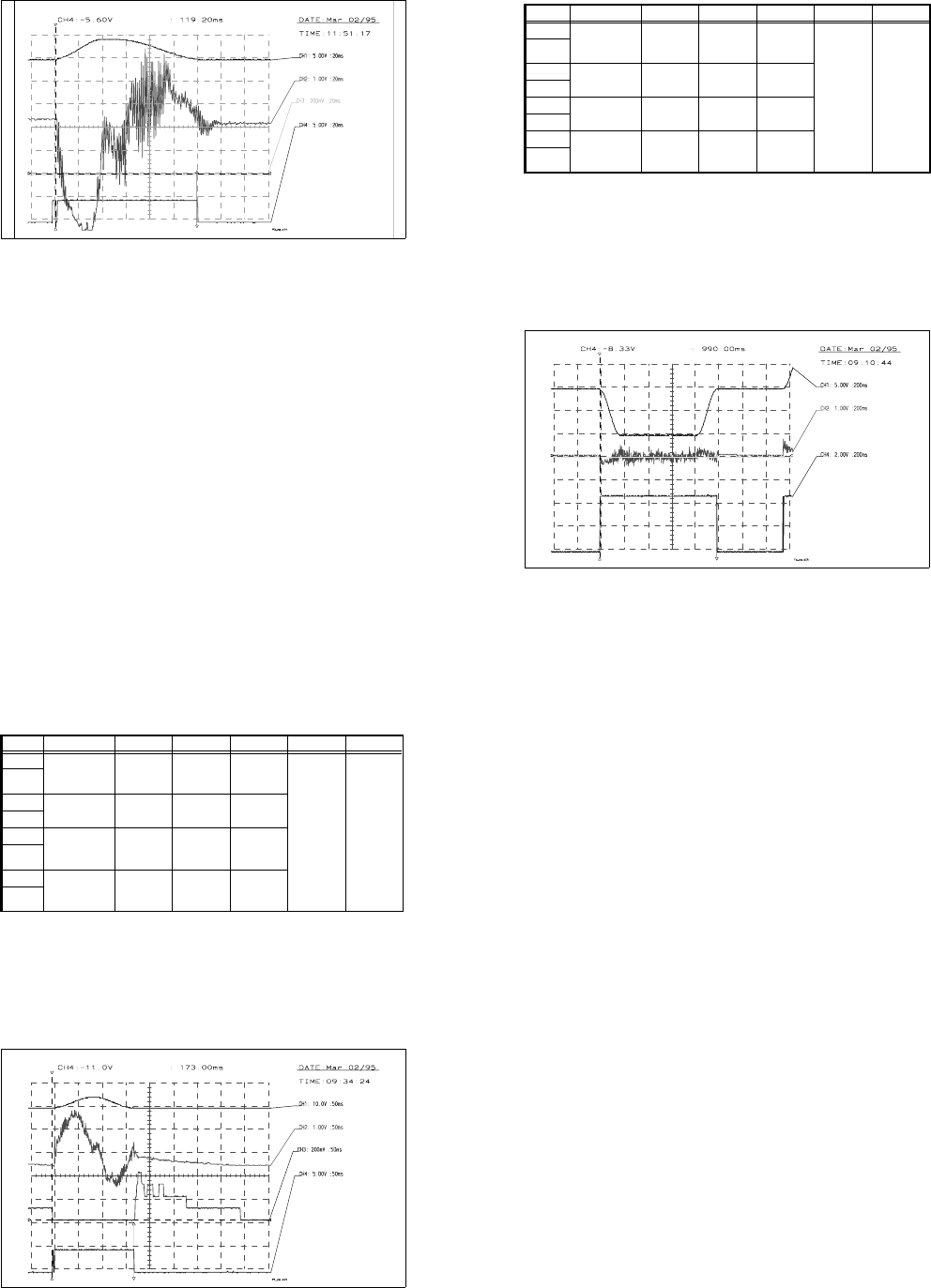
Fig. 10.3.15 Setpoint value curve for adjusting the speed of the X axis
Input Test point Signal Coupling Y deflection Trigger X deflection
CH1 Axis test box,
setpoint value
BNC socket
Setpoint
value
DC 5.00 V/Div
CH4
10%
pre-trigger
200 ms
GND
CH2
Control unit
f/V converter
Signal from
f/V converter
DC 1.00 V/Div
GND
CH3
GND
CH4 Axis test box,
end signal
BNC socket
End signal DC 2.00 V/Div
GND
Tab. 10.3.7 Oscilloscope settings: Adjusting the speed of the X axis
Vnom. value
f/V converter signal
End signal
Adjust f/V converter signal to 0
If distance: 100000-300000
v: 10 accel.: 150 decel.: 150
time approx. 990ms +- 15ms
10 Siplace G automatic glue applicator SIPLACE 80S/80F/G Service Manual
Edition 06/98
10 - 54
Adjusting the P gain (see Fig. 10.3.16)
Preparation:
● Set the MA data as for adjusting the speed (see Table 10.3.2)
● Set the axis to continuous operation from 195,000 to 205,000.
Setting:
● Use the servo board potentiometer to increase the P gain until a slight tendency to vibrate occurs
at the position deviation.
● Reduce or increase the P gain until the position deviation no longer rises or dips (see Fig.
10.3.16).
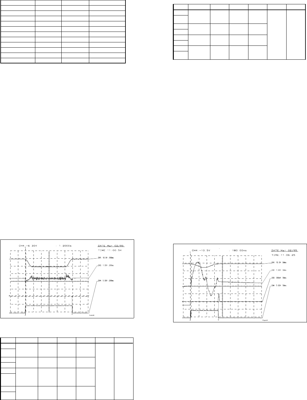
Fig. 10.3.16 Setpoint value curve for adjusting the P gain for the X axis
Input Test point Signal Coupling Y deflection Trigger X deflection
CH1 Axis test box,
setpoint value
BNC socket
Setpoint
value
DC 5.00 V/Div
CH4
10%
pre-trigger
200 ms
GND
CH2
Test point 6,
servo board
Actual cur-
rent value
DC 1.00 V/Div
GND
CH3 Axis test box,
position devia-
tion BNC socket
Position
deviation
DC 200 mV/Div
GND
CH4 Axis test box,
end signal
BNC socket
End signal DC 2.00 V/Div
GND
Tab. 10.3.8 Oscilloscope settings: Adjusting the P gain for the X axis
Vnom value
MP6 current curve of servo board
Position deviation
End signal
P gain OK
If distance: 205000-195000
V: 10 accel.: 150 decel.: 150
SIPLACE 80S/80F/G Service Manual 10 Siplace G automatic glue applicator
Edition 06/98
10 - 55
Check:
● Set the positioning distance to 120,000-280,000 and 100,000-300,000.
● The position deviation and current curve must not rise for either distance.
● During the reference sequence, the axis must not rise or give off a loud humming noise.
● The positioning time for the distance 120,000 to 280,000 must be 815 ms ±10 ms.
● The positioning time for the distance 100,000 to 300,000 must be 980 ms
±
10 ms.
Positioning quality
Preparation:
● Reset the MA data to basic data (see Table 10.3.4) and reference the axis.
● Set the distance in accordance with the distance table (see Table 10.3.9) and check the position
deviation.
● 50ms after the end signal, the position deviation must not exceed 5 digits.
Check:
● Set the distance in accordance with the distance table and check the time. Check the settings and
the machine, if necessary.
● The end signal will not be output until the post-pulse oscillations in the position deviation have
fallen below the specified value (position deviation in REAL.MA), since this could cause signifi-
cant fluctuations in the positioning time.
10 Siplace G automatic glue applicator SIPLACE 80S/80F/G Service Manual
Edition 06/98
10 - 56
Checking the offset
See "Adjusting the offset".
Reset the MA data to basic data (see Table 10.3.4) and reference the axis.
10.3.6.6 Y axis, SIPLACE G
General preparatory work
● The gluing heads and cameras must be fitted in order to set the axes.
● Use an RC filter to record the current curve and the diagnostic strip test point signal.
● Carry out a head and Y axis reference sequence.
● Position the X axis at 200,000.
● Reference the Y axis
● Switch the machine on for approximately 30 minutes.
Setting the offset
Preparation:
● Connect an axis test box to the axis board and set the position display to axis number 1.
● Change the MA data for offset adjustment and reference the axis (see Table 10.3.1).
● Position the Y axis at 500,000.
Setting:
● Use the offset potentiometer on the servo board to set the axis position to 500,000
±
1 digit.
Check:
● The axis position display should not deviate from the value 500,000 by more than 1 digit.
Positions Setpoint time in ms Tolerance in ms Setting range in ms
199,900 - 200,100 55 10 45 - 65
199,800 - 200,200 75 15 60 - 90
199,600 - 200,400 80 10 70 - 90
199,000 - 201,000 105 15 90 - 120
198,000 - 202,000 125 15 110 - 140
197,000 - 203,000 145 15 130 - 160
195,000 - 205,000 175 15 160 - 190
190,000 - 210,000 250 15 235 - 265
175,000 - 225,000 385 15 370 - 400
150,000 - 250,000 595 15 580 - 610
100,000 - 300,000 1005 15 990 - 1020
Tab. 10.3.9 Distance table for the X axis, SIPLACE G
SIPLACE 80S/80F/G Service Manual 10 Siplace G automatic glue applicator
Edition 06/98
10 - 57
Setting the speed (see Fig. 10.3.17)
Preparation:
● Change the MA data for adjusting the speed (see Table 10.3.2) and reference the axis.
● Connect an axis test box to the axis board and set to time measurement - axis 1.
● Set the axis to continuous operation for a distance of 300,000 - 550,000 digits.
Setting:
● Increase the P gain on the servo board until the axis can be easily positioned.
● Use the tacho potentiometer on the Y-servo board to set the f/V converter signal to the zero line
±500mV (see Fig. 10.3.17) once the speed is reached (maximum setpoint values).
Check:
● The positioning time must be 1200ms ± 15ms (time measured with a suitable P gain).
Input Test point Signal Coupling Y deflection Trigger X deflection
CH1 Axis test box,
setpoint value
BNC socket
Setpoint
value
DC 5.00 V/Div
CH4
10%
pre-trigger
200 ms
GND
CH2
Control unit,
f/V converter
Signal from
f/V converter
DC 1.00 V/Div
GND
CH3
GND
CH4 Axis test box,
end signal
BNC socket
End signal DC 2.00 V/Div
GND
Tab. 10.3 - 10 Oscilloscope settings: Setting the speed of the Y axis
10 Siplace G automatic glue applicator SIPLACE 80S/80F/G Service Manual
Edition 06/98
10 - 58
Fig. 10.3.17 Setpoint value curve for adjusting the speed of the Y axis
Adjusting the P gain (see Fig. 10.3.18)
Preparation:
● Set the MA data as for adjusting the speed (see Table 10.3.2).
● Set the axis to continuous operation for a distance of 395,000-405,000 digits.
Setting:
● Use the potentiometer on the servo board to increase the P gain until a slight tendency to vibrate
can be seen in the position deviation (see Fig. 10.3.18).
Input Test point Signal Coupling Y deflection Trigger X deflection
CH1 Axis test box,
setpoint value
BNC socket
Setpoint
value
DC 5.00 V/Div
CH4
10%
pre-trigger
200 ms
GND
CH2
Test point 6,
servo board
Actual cur-
rent value
DC 1.00 V/Div
GND
CH3 Axis test box
position devia-
tion BNC
socket
Position
deviation
DC 200 mV/Div
GND
CH4 Axis test box,
end signal
BNC socket
End signal DC 2.00 V/Div
GND
Tab. 10.3 - 11 Oscilloscope settings: adjusting the P gain for the Y axis
Vnom value
f/V converter signal
End signal
Adjust f/V converter signal to 0
If distance: 550000-300000
v: 10 accel.: 200 decel.: 200
SIPLACE 80S/80F/G Service Manual 10 Siplace G automatic glue applicator
Edition 06/98
10 - 59
● Reduce or increase the P gain until the position deviation no longer rises or dips.
Fig. 10.3.18 Setpoint value curve for the P gain for the Y axis
Check:
● Set the positioning distance to 350,000 - 450,000 and 300,000 - 500,000.
● The position deviation and current curve must not rise at either distance.
● During the reference sequence, the axis must not rise or give off a loud humming noise.
● Set the axis to continuous operation for a distance of 350,000 - 450,000 digits: positioning time
approximately 580
±
10ms
● Set the axis to continuous operation for a distance of 300,000 - 500,000 digits: positioning time
approximately 990 ±10ms
Positioning quality
Preparation:
● Reset the MA data to basic data (see Table 10.3.4) and reference the axis.
● Set the distance in accordance with the distance table (see Table 10.3.12) and check the position
deviation.
● 50ms after the end signal, the position deviation must not exceed 5 digits.
Check:
● Set the distance in accordance with the table (see Table 10.3.12) and check the time. Check the
settings or the machine, if necessary.
● The end signal will not be output until the post-pulse oscillations in the position deviation have
fallen below the specified value (position deviation in REAL.MA), since this could cause signifi-
cant fluctuations in the positioning time.
Vnom value
MP6 current curve of servo board
Position deviation
End signal
P gain OK
If distance: 395000-405000
v:10
Acceleration.: 200
Deceleration.: 200
10 Siplace G automatic glue applicator SIPLACE 80S/80F/G Service Manual
Edition 06/98
10 - 60
Checking the offset
See "Adjusting the offset".
Reset the MA data to basic data (see Table 10.3.4) and reference the axis.
Distance
Setpoint time in
ms
Tolerance in ms Setting range in ms
399,900 - 400,100 50 15 35 - 65
399,800 - 400,200 70 25 45 - 95
399,600 - 400,400 70 15 55 - 85
399,000 - 401,000 105 10 95 - 115
398,000 - 402,000 130 10 120 - 140
397,000 - 403,000 150 10 140 - 160
395,000 - 405,000 180 10 170 - 190
390,000 - 410,000 255 15 240 - 270
375,000 - 425,000 390 15 375 - 405
350,000 - 450,000 595 15 580 - 610
300,000 - 500,000 1005 15 990 - 1020
Tab. 10.3.12 Ddistance table for the Y axis, SIPLACE G
SIPLACE 80S/80F/G Service Manual 10 Siplace G automatic glue applicator
Edition 06/98
10 - 61
10.4 Setting the symmetry and amplification of the
track signals
10.4.1 Basic test set-up
● Prepare the automatic placement machines for the measurement as follows:
- Switch ON at the main switch
- Open the protective cover
- Use a (plastic) feeler gauge to set the air gap between the scanning head (sensor head of the measuring
system) and the track rule to 0.4 mm +
0.05 mm. Check this setting at the start, middle and end of the
travel range.
- Plug in the jumper for the counting direction (see Fig. 10.4.2 and Fig. 10.4.3).
Fig. 10.4.1 Position of the boards to be measured Y0055 and Y0004
Key to Fig. 10.4.1
1) Large axis conversion board Y0004 2) Gluing heads
3) Small axis conversion board Y0055 4) Gantry conversion board Y 0053
5) Gluing head control board Y0054
➀
➁
➂
➃
➄
10 Siplace G automatic glue applicator SIPLACE 80S/80F/G Service Manual
Edition 06/98
10 - 62
Fig. 10.4.2 Basic test set-up
PLEASE NOTE
The protective earth in the mains plug of the oscilloscope must not be insulated or clamped.
● To measure the Y axis, connect the connecting cable of the tester measuring system to plug X11 on the
large axis conversion board Y0004 (see Fig. 10.4.3).
● To measure the X axis, connect the connecting cable of the tester measuring system to plug X 28 on the
small axis conversion board Y 0055 (see Fig. 10.4.4).
.....
Messsystem X - Y
Ah
X 11 / X 28
Spur A / B / RI
Platine Y0004 / Y0055
BNC - Leitung
Flachbandanschlusskabel
Siplace G
Auflösung des Massstabes:
01
1 Digit = 0,0025 mm
CH1 CH2
X
Y
Track signal tester
RI
Track
AB
Tracks A / B / RI
PC board Y0004 / Y0055
Scale resolution
1 Digit = 0.0025 mm
Flat ribbon conn. cable
Track signal tester
X-Y measurement system
SIPLACE 80S/80F/G Service Manual 10 Siplace G automatic glue applicator
Edition 06/98
10 - 63
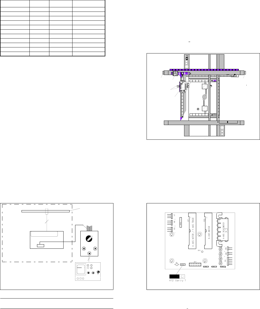
Fig. 10.4.3 Large axis conversion board Y0004, PS 8
Key to Fig. 10.4.3
Test points X 11:
- X 11, 4/6 input of RSF 1,2 V
PP
+ 0.1V R 48: Amplitude of track A
- X 11, 5/7 output of amplifier 1.8 V
PP
R 33: Offset of track A
- X 11, 1/2/3 output of 5V gate, square-wave R 15: Amplitude of track B
- X 12: Jumper for counting direction R 29: Offset of track B