80S-15贴片机.pdf - 第475页
11 Control Unit SIPLACE 80 S/F/G Service M anual Edition 04/97 11 - 6 11.1.5 Replacing the Hard Disk / F loppy Disk Board Spare p arts Floppy/win ches ter AMS-M 349-A100 , from item no. 0 0319704 -01 ● Disconn ect all pl…
SIPLACE 80 S/F/G Service Manual 11 Control Unit
Edition 04/97
11 - 5
11.1.4 Replacing Station Computer M34
Spare parts
KSP-M34-A162 computer, from item no. 00302834-07
●
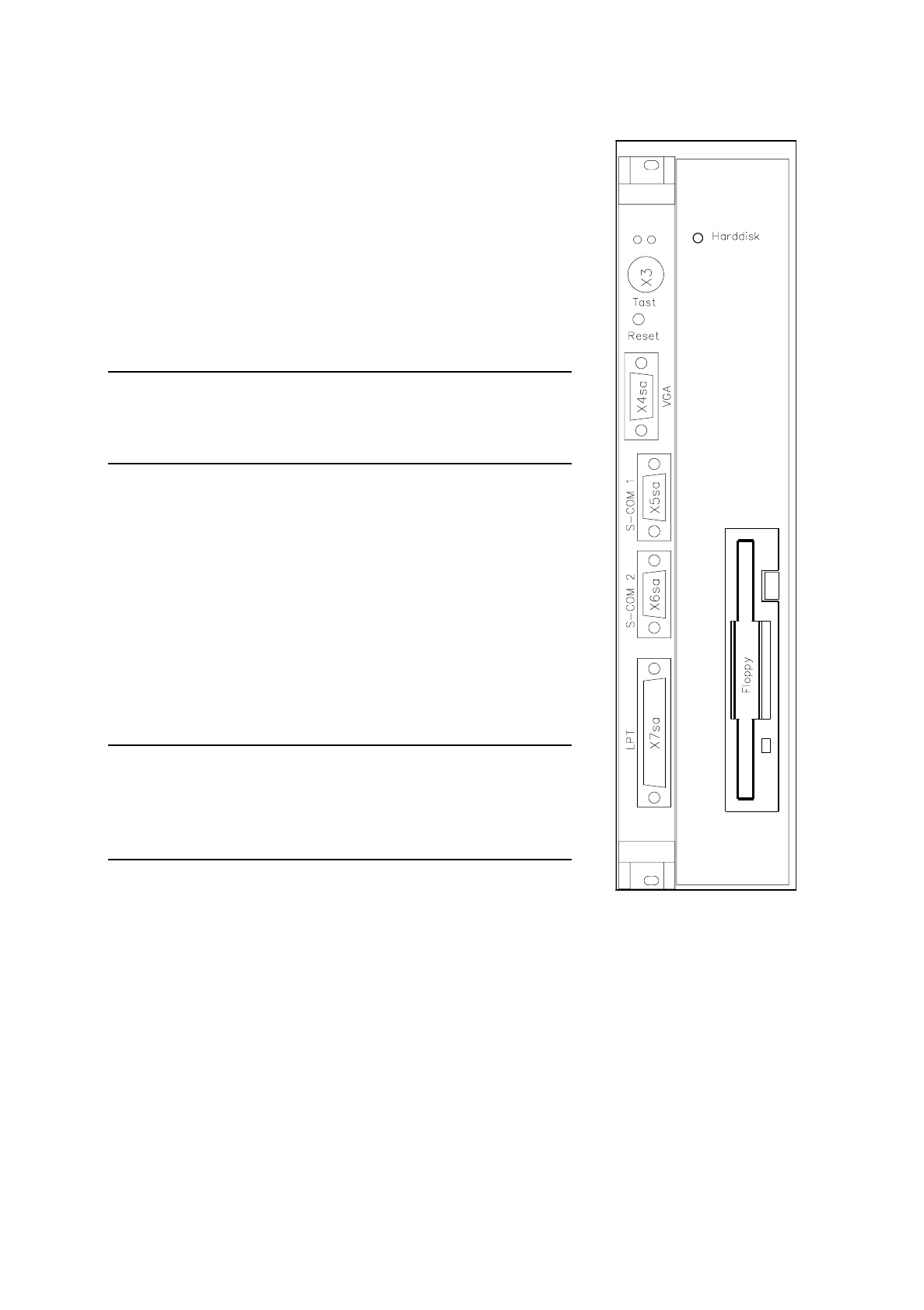
Disconnect all plug-in connections on the front cover of the sta-
tion computer (plugs x3, x4 sa, x5 sa; see Fig. 11.1.2).
●
Undo the station computer board’s front cover mounting screws
(2 slotted-head screws) and the hard disk / floppy disk board
mounting screws (4 slotted head screws).
NOTE
The station computer and the hard disk / floppy disk boards are
connected via two short ribbon cables.
●
Carefully pull out the station computer board and the hard disk /
floppy disk boards simultaneously.
●
Place the boards on an ESD-checked surface.
●
Check the wrap wiring of the new station computer against the
list (see Section 11.3).
●
Disconnect the connecting cable between the station computer
and the hard disk / floppy disk board.
●
Connect the new station computer board to the hard disk / floppy
disk board.
●
To fit the boards proceed in the reverse sequence of operations.
NOTE
When inserting the connecting plugs make sure you have the cor-
rect slots on the front panel.
Should you have lost the setup data for the M34 see Section 11.2.
Fig. 11.1.2 M34 computer -
hard disk/floppy disk

11 Control Unit SIPLACE 80 S/F/G Service Manual
Edition 04/97
11 - 6
11.1.5 Replacing the Hard Disk / Floppy Disk Board
Spare parts
Floppy/winchester AMS-M349-A100, from item no. 00319704-01
●
Disconnect all plug-in connections on the front panel of the station computer (plugs x3, x4 sa, x5 sa; see Fig.
11.1.2).
●
Unscrew and remove the MC board’s front cover mounting screws (2 slotted-head screws) and the hard disk /
floppy disk board mounting screws (4 slotted-head screws).
NOTE
The station computer and the hard disk / floppy disk boards are connected via two short flat ribbon cables.
●
Carefully pull out the station computer and hard disk / floppy disk boards. Place the boards on an ESD-
checked surface.
●
Disconnect the connecting cables between the boards (see the section
Replacing Computer M34
).
●
Insert the new hard disk / floppy disk board in the station computer board.
●
To fit the boards proceed in the reverse sequence of operations.
NOTE
When inserting the connecting plugs make sure you have the correct slots on the front panel. Should you have
lost the setup data for the M44 see Section 11.2.
●
Switch the machine on and install the current station software (see
Adjustment instructions
).
●
Copy the original MA data from the backup copy onto the hard disk.

SIPLACE 80 S/F/G Service Manual 11 Control Unit
Edition 04/97
11 - 7
11.2 Set-Up Configuration of the M34 Station Computer
NOTE
To change the data you will need to use the numerical keypad. This is included in a normal keyboard. The
keys are marked with violet numbers and characters in their top left corner (for example, keys 7-0, U-P, J-ö,
and so on).
Press the Fn key to activate the numerical keypad function of the individual keys.
11.2.1 Configuration Data
11.2.1.1 Screen 1
Date: dd. mmm yyyy
Time: hh:mm:ss
Drive A: 1.44, 3 ½ in.
Drive B: None
Video: EGA / VGA
Post message: Maximize
Quick boot: Disable
Halt on: ALL errors
Security: Disable
Virus Warury: Disable
Booting sequence: A, C
Default speed: High
Disk 0 49 (automatic hard disk detection)
Disk 1 None