80S-15贴片机.pdf - 第234页
7 Components Table S IPLACE 80 S/F/G Servic e Manual Edition 04/97 7 - 52 Fig. 7.6.7 Checking the spring bows in the empty tape channel (guide pl ate, inner)

SIPLACE 80 S/F/G Service Manual 7 Components Table
Edition 04/97
7 - 51
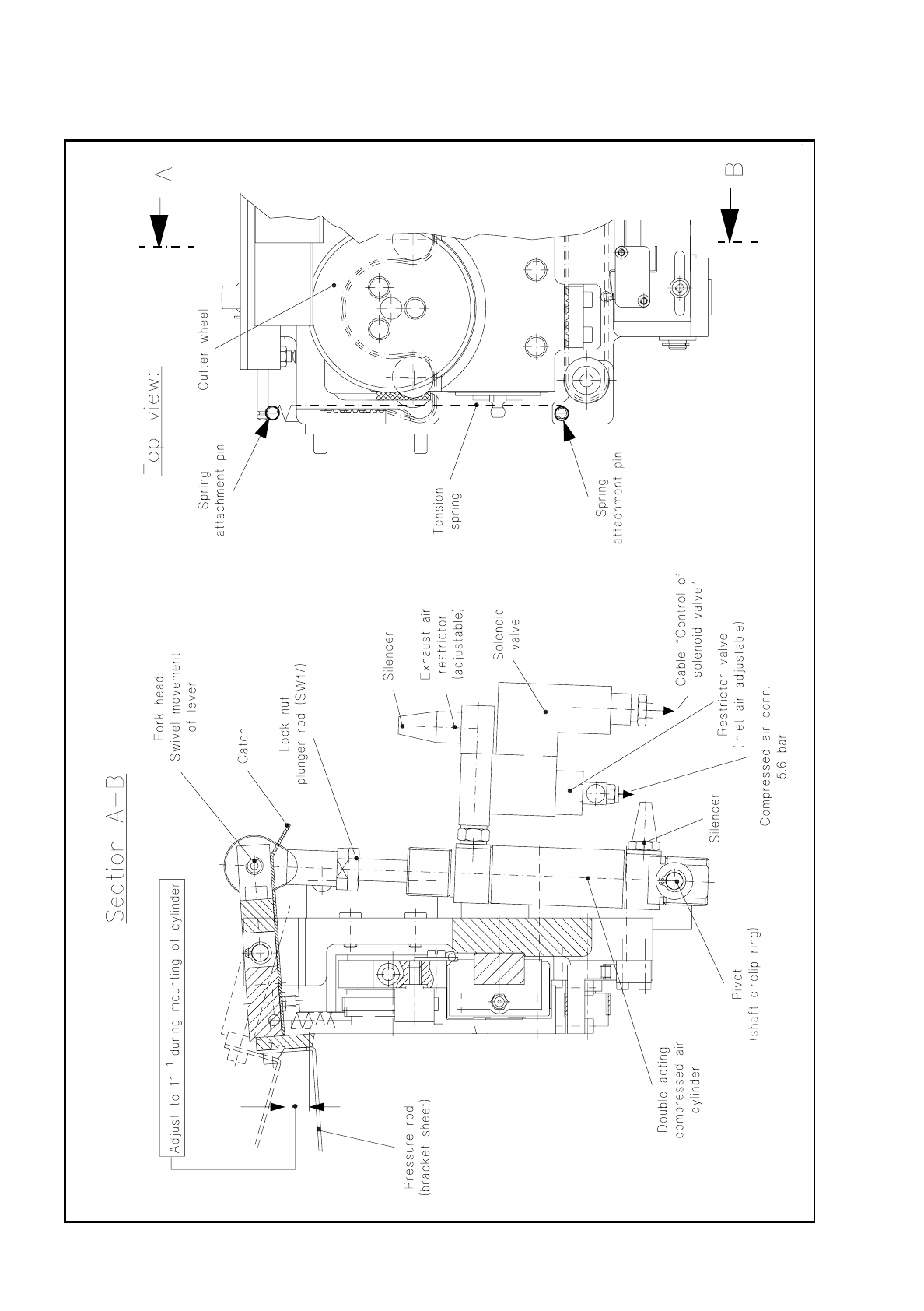
7.6.12.3 Replacing the Solenoid Valve or Compressed Air Cylinder
For the following work the tape cutting unit can remain installed in the machine.
●
In the course of fault location (see above) the machine has already been switched off and the components
changeover table removed.
●
For detailed information on the location, removal and installation of the solenoid valve and, if applicable, of
the compressed air cylinder, refer to Fig. 7.6.7.
●
When installing or replacing the solenoid valve make sure that the regulators are in their correct assigned
positions:
exhaust air restrictor should be at the compressed air cylinder, the restrictor valve at the supply connection
of the solenoid valve, as shown in Fig. 7.6.6 and Fig. 7.6.7. The Item Nos. of the regulator will be found
under "Spare Parts".
NOTE
The 3/2-way solenoid valve is an alternating current solenoid valve which is connected in parallel with the
motor and operated with 22V. It is reset by spring power.
●
After replacing the compressed air cylinder, insert the shaft circlips of the cylinder and fork-joint pivot into
the annular groove on the shaft. Adjust the swivel movement of the pressure rod as described below.
●
Carry out all operations described in section 7.6.15 „Concluding Work“ on page 7 - 55.
7.6.12.4 Adjusting the Swivel Movement, Replacing the Tension Springs
If the swivel movement is faulty, once you have excluded a fault in the compressed air branch (see above)
check the setting and the tension springs as follows:
●
In the course of fault location (see above) the machine has already been switched off and the components
changeover table removed.
●
Swivel movement of the pressure rod: correct the swivel movement by making the corresponding change
in the position of the fork head on the plunger rod (see Fig. 7.6.7):
●
When slackening off the lock nut (SW17) hold the fork head stationary with your second open-ended
spanner (SW17), and adjust the swivel movement to dimension 11 +1 mm (see Fig. 7.6.7).
●
Lock the fork head into this position.
●
Replacement of the tension springs: With the tape cutting unit installed, it is hard to get at the lefthand ten-
sion spring (see Fig. 7.6.7). For this reason, you should remove the empty tape cutting unit from the
machine base as described in the section 7.6.6 "Checking and Replacing the Cutter Wheel and Cutter
Strip".
●
Detach the two tension springs on the left and right of the tape cutting unit (see Fig. 7.6.7 or Fig. 7.6.4)
and fit the new tension springs into the annular groove of the spring attachment pins.
●
Reinstall the tape cutting unit, aligning it symmetrically to the empty tape channel (see below, section
7.6.14 "Fitting and Aligning the Empty Tape Cutting Unit and Empty Tape Channel").
●
Carry out all steps described in "Concluding work". In this section there is a description of checking and
adjusting the swivelling speed (inward and outward movements).
7 Components Table SIPLACE 80 S/F/G Service Manual
Edition 04/97
7 - 52
Fig. 7.6.7 Checking the spring bows in the empty tape channel (guide plate, inner)
SIPLACE 80 S/F/G Service Manual 7 Components Table
Edition 04/97
7 - 53
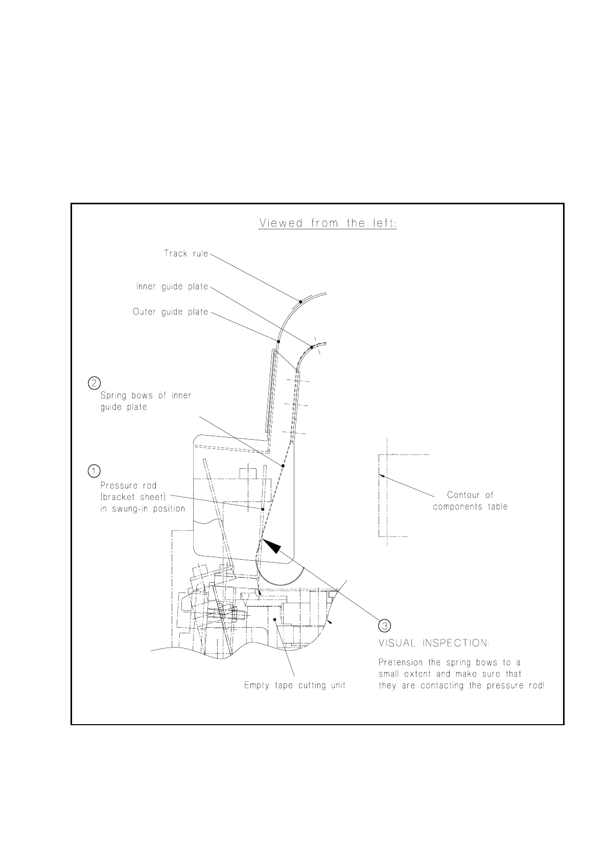
7.6.13 Empty Tape Channel: Checking and Replacing the Spring Bows
If individual tapes are not being cut (tape jam in individual feeder modules), this may be due to the "guide
plate, inner" having bent spring bows.
●
To check the spring bows proceed as shown in Fig. 7.6.8.
●
If individual spring bows are bent, install a new "empty tape channel complete".
●
Adjust the new empty tape channel so that it is positioned symmetrically to the pressure rod (see below).
Fig. 7.6.8 Aligning the empty tape channel to the pressure rod when refitting