80S-15贴片机.pdf - 第432页
9 Revolver Head SIPLACE 80S/F/G Service Manual Edition 04/97 9 - 148 ● Insert th e BERO a nd set the operatin g dist ance as d escribed for the BE RO of sc rewdri ver 1 in Fig. 9.1 8.4 on page 9 - 137. ● Make su re that …
SIPLACE 80S/F/G Service Manual 9 Revolver Head
Edition 04/97
9 - 147
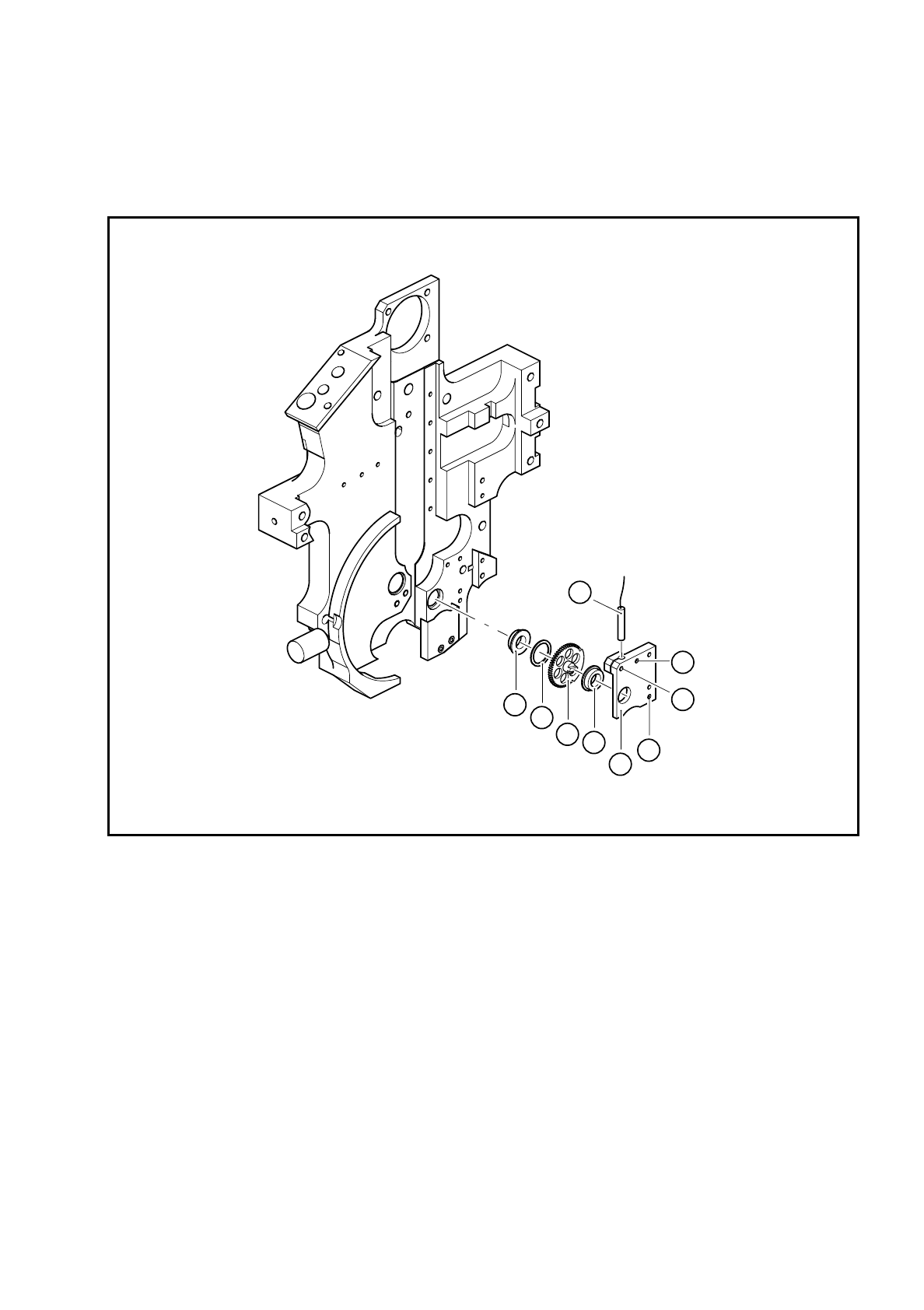
9.19.7 Replacing the miniature ball bearing, spring washer and toothed
wheel 2 ’reject’
Fig. 9.19.5 Replacing the miniature ball bearing, spring washer and toothed wheel 2 ’reject’
Key to Fig. 9.19.5
●
Loosen the M1.6x4 BERO clamping screw.
●
Pull the BERO out of the hole.
●
Loosen the two M2x6 fillister head screws (see item 7 in Fig. 9.19.5) for fixing the toothed wheel holder
(see item 5 in Fig. 9.19.5).
●
Carefully pull the toothed wheel holder away from the parallel pins.
●
Replace the miniature ball bearing, spring washer or toothed wheel 2.
●
Align the screwdriver blade with respect to toothed wheel 1 as shown in Fig. 9.19.2 on page 9 - 143.
●
Fix the toothed wheel holder in place.
1 5x8x2.5 MF85 ZZS miniature ball
bearing
5 Toothed wheel holder
2 Spring washer FS 8 x 10 6 M1.6x4 fillister head screw for clamping the BERO
3 Toothed wheel 2 - reject 7 M2x6 fillister head screw for fixing the toothed wheel
4BERO holder
4
5
1
1
2
3
6
7
7

9 Revolver Head SIPLACE 80S/F/G Service Manual
Edition 04/97
9 - 148
●
Insert the BERO and set the operating distance as described for the BERO of screwdriver 1 in Fig. 9.18.4
on page 9 - 137.
●
Make sure that you align the screwdriver blade with the 30° mark when you assemble the head. If it is not
aligned, the star will not be able to turn the segments after assembly.
●
After assembly, check the functioning of screwdriver 2 with reference to the adjustment instructions and
using the SITEST program.

SIPLACE 80S/F/G Service Manual 9 Revolver Head
Edition 04/97
9 - 149
9.20 Service work on the sz axis
9.20.1 Tools, equipment and consumables
9.20.2 Spare parts
9.20.3 Replacing the DC servo motor
DANGER
OOO
Switch the placement machine off at the main switch and disconnect from the power supply.
●
Remove all the segments using the appropriate segment changing device and place the segments in the
segment case.
From item number
Set of screwdrivers
Set of hexagon socket-head screwdrivers
Open-end spanner, size 10
Diagonal cutter
Hot air gun
0.15 mm feeler gauge
SIPLACE segment changing device, version I
00310699-01
SIPLACE segment changing device, version II
00305897-02
Segment case
00302217-01
Adjustment instructions
SITEST program
Circuit diagrams
Cable ties
Shrink-fit hose
From item number
DC servo motor 28 GTD 28 and incremental shaft encoder
00201299-01
Completely assembled cam
00201209-01
3 RG 4603 2AB00/3.0 mm/SN = 0.6 mm/1S BERO
00303945-01