80S-15贴片机.pdf - 第421页
SIPLACE 80S/F/G Service Manual 9 Revolver Head Edition 04/97 9 - 137 Fig. 9. 18.3 B ERO of screwdriver 1 Fig. 9. 18.4 Wiring diagr am for the ’Sc rewdriver 1’ BERO on conversion board Y0307 Key to F ig. 9 .18.4 1 + 24 V:…

9 Revolver Head SIPLACE 80S/F/G Service Manual
Edition 04/97
9 - 136
9.18.4 Replacing the stop
●
Loosen the two M1.6 x 8 countersunk screws for fixing the cover plate (see item 2a in Fig. 9.18.1) and stop
(see item 2 in Fig. 9.18.1).
●
Reverse the above sequence to install.
PLEASE NOTE:
After assembly, the star can only turn the segments if the head was assembled while the screwdriver
blade was in the horizontal position (see item 2 in Fig. 9.18.2).
●
Check the functioning of screwdriver 1 with reference to the adjustment instructions and using the SITEST
program.
9.18.5 Replacing toothed wheel 1
Dismantling and assembly of toothed wheel 1 are described in Section 9.18.3 on page 9 - 133. When assem-
bling the toothed wheel, pay particular attention to the position of the screwdriver blade with respect to the
toothed wheel, as shown in Fig. 9.18.2 on page 9 - 135.
9.18.6 Replacing the BERO
●
Loosen the M 1.6 x 4 fillister head screws for fixing the cable brackets (see item 4 in Fig. 9.18.3).
●
Loosen the M 1.6 x 4 fillister head screws (see item 2 in Fig. 9.18.3) for clamping the BERO (see item 1 in
Fig. 9.18.3).
●
Cut the connecting cable to the BERO and pull the BERO out of the hole.
●
Remove the board cover (see item 5 in Fig. 9.18.3).
●
Unsolder the connecting cable from the BERO to the conversion board Y0307 (see items 1, 2 and 3 in Fig.
9.18.4).
CAUTION
OO
Do NOT dismantle the lifting carriage when you replace the cable. Otherwise you will have to return the
head to the factory to be reset.
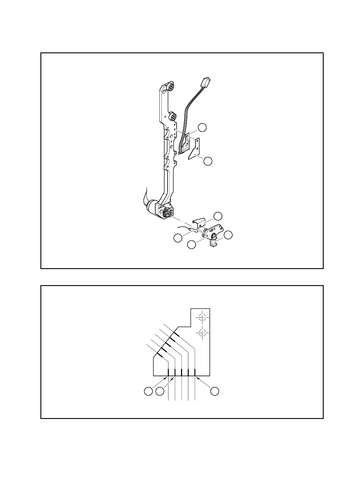
Key to Fig. 9.18.3
1 BERO
2 M 1.6 x 4 fillister head screws for clamping the BERO
3 Segment claw
4 Cable bracket
5 Board cover
6 ’Screwdriver 1’ conversion board Y0307
SIPLACE 80S/F/G Service Manual 9 Revolver Head
Edition 04/97
9 - 137
Fig. 9.18.3 BERO of screwdriver 1
Fig. 9.18.4 Wiring diagram for the ’Screwdriver 1’ BERO on conversion board Y0307
Key to Fig. 9.18.4
1 + 24 V: brown
2 GND 24 V: blue
3 BERO signal: black
5
6
4
2
1
3
3
1 2
9 Revolver Head SIPLACE 80S/F/G Service Manual
Edition 04/97
9 - 138
●
Solder the connecting wires of the new BERO to the cut cable ends of the old BERO.
●
Carefully pull the new cable with the old cable through the cable duct in the lifting carriage.
●
Solder the connecting wires of the new BERO to conversion board Y0307 as shown in Fig. 9.18.4.
●
Place the BERO in the hole.
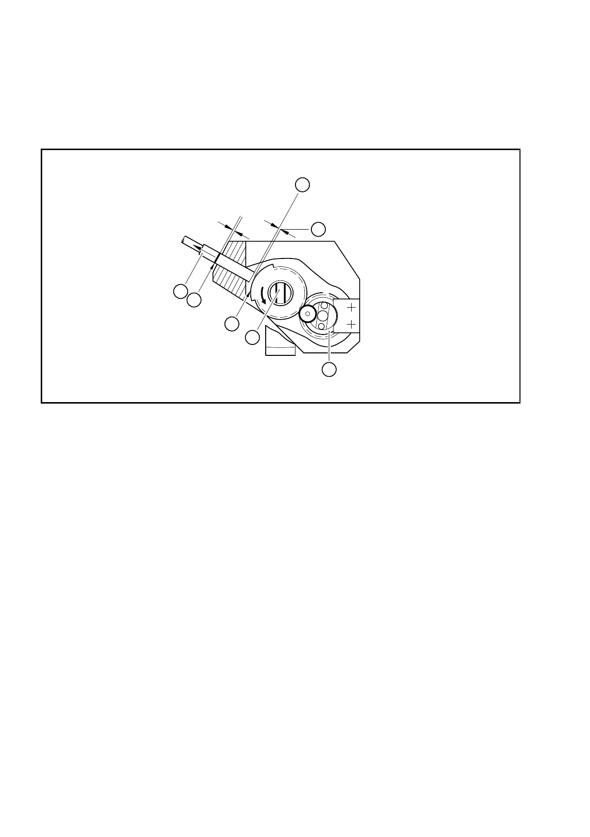
Fig. 9.18.5 Setting the BERO operating distance for screwdriver 1
Key to Fig. 9.18.5
●
Set the BERO operating distance.
–
Turn toothed wheel 1 (see item 4 in Fig. 9.18.5) until the screwdriver blade (see item 5 in Fig. 9.18.5)
is vertical.
–
Push the BERO (item 1 in Fig. 9.18.5) in until it touches the trigger surface (see item 3 in Fig. 9.18.5).
–
Use the scribing iron to carefully mark the BERO.
–
Pull the BERO back slightly and use a feeler gauge to measure a distance of 0.2 mm.
–
Clamp the BERO in this position.
–
When assembling the head, make sure that the screwdriver blade is horizontal. If it is not horizontal,
the star will not be able to turn the segments after assembly (see item 2 in Fig. 9.18.2).
●
After assembly, check the functioning of screwdriver with reference to the adjustment instructions and
using the SITEST program.
1 BERO 5 Screwdriver blade
2 Mark on the BERO made with the scribing iron 6 Operating distance 0.2 mm
3 Trigger surface of the toothed wheel 7 BERO trigger surface
4 Toothed wheel 1
3
0,2mm
0,2mm
7
6
4
5
2
1