80S-15贴片机.pdf - 第338页
9 Revolver Head SIPLACE 80S/F/G Service M anual Edition 04/97 9 - 54 Fig. 9.6.8 Docking the turning station at the segmen t friction wheel 9.6. 3.2 Opto-Electronic Scanner Unit of dp1 and dp2 The pos ition of th e nozzle…

SIPLACE 80S/F/G Service Manual 9 Revolver Head
Edition 04/97
9 - 53
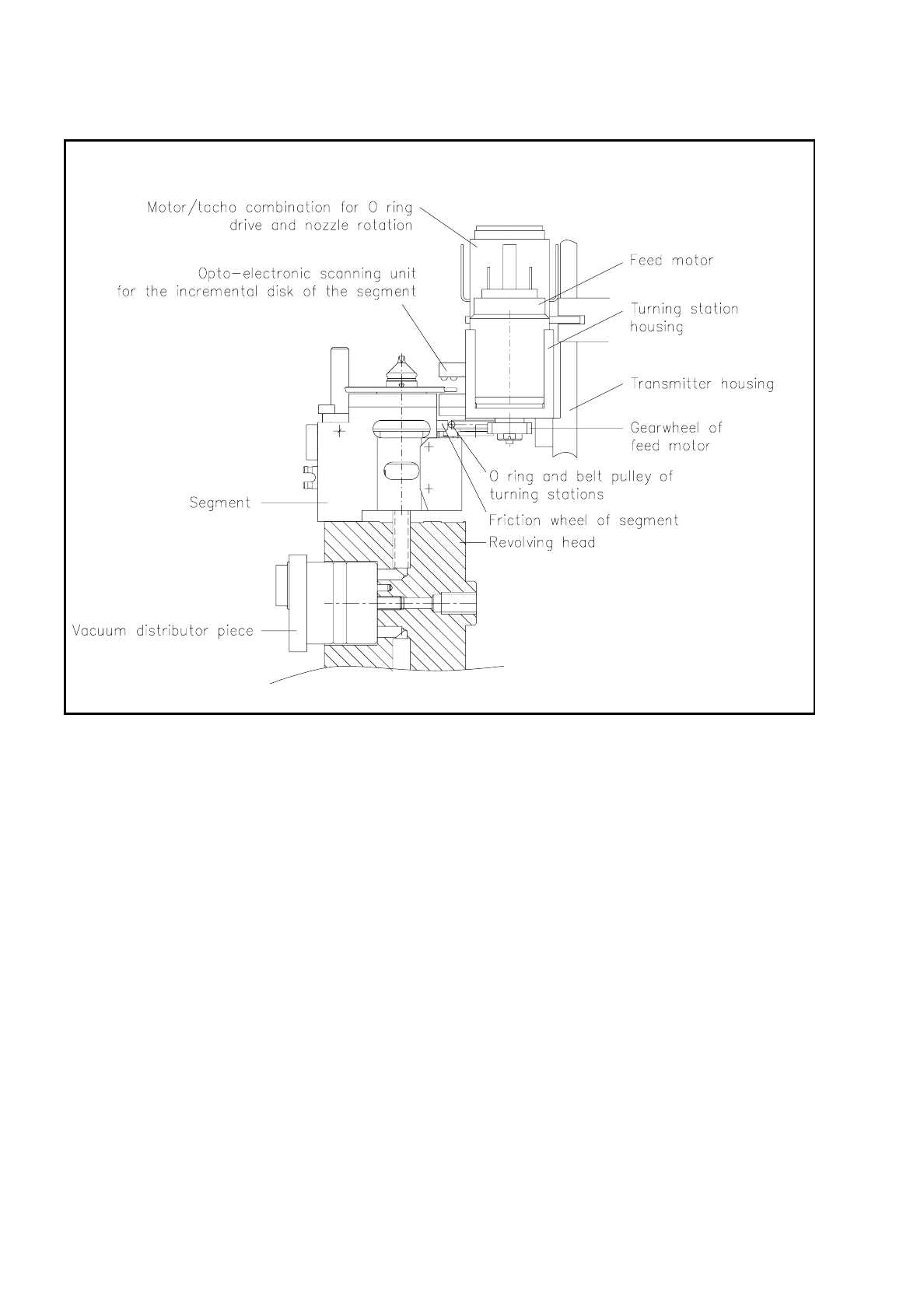
9.6.3.1 Structure and Function of the Turning Station
Both turning stations, dp1 and dp2, are fitted at the rear of the encoder housing, in other words, the side fac-
ing the lifting slide. In each case an adjustment plate ensures the precise setting of each turning station.
The housing of each turning station is fastened to the encoder housing with two M3 hexagon socket-head
screws from the front of the encoder housing (see Fig. 9.6.7). The slotted screws for fastening the beros are
also accessible from the front of the encoder housing. The fastening screw for dp2 is however not accessible
until the amplifier board has been removed. The encoder housing has two cutouts to allow the conversion
board "Rotate nozzle" of each turning station to be plugged into the corresponding connectors on the "Head"
conversion board.
The feed motor is a d.c. motor and via gearwheel and toothed rack looks after the swivel movement of the
turning station. The feed motors are operated by the motor controller board Y0009.
The bero of each turning station signals the swung-out state - in other words, the turning station has decou-
pled from the segment - as the "active high" state. The turning station is held in its end positions - swung in or
swung out - by means of a holding current at the feed motor. The swinging-in movement, that is, the docking
of the belt pulley and o-ring at the friction wheel of the segment, can only take place when the segment is cor-
rectly positioned in the revolver head station in question - in other words, the end message from the dR
revolver head axis has been received. The swinging-in movement releases the brake which holds the sleeve
in its position.
The motor-tacho combination of the turning station drives the o-ring for the rotational movement of the sleeve
and nozzle of the segment as soon as the turning station has docked with the o-ring at the friction wheel of the
segment. Control of the rotational movement is a closed-loop control circuit with the following components:
–
The axis controller card receives the corresponding machine data from the machine controller, such as, for
example, angle of rotation, motor current and voltage, operating mode, and so on. This operates the servo
amplifier in the servo unit which in turn supplies the drive motor for the rotational movement with the corre-
sponding current and voltage values.
–
The tachometer generator of the turning stations supplies the servo amplifier with the current speed values
for regulating current and voltage.
–
The incremental disk of the segment is scanned by the opto-electrical scanning unit of the turning station.
It supplies the information for the current position of the sleeve and nozzle and returns these data to the
axis controller card. This is where a comparison between the setpoint and actual values is made. The
result of this comparison is passed on as control information to the servo amplifier.
Once the required rotational position of the nozzle has been reached, the turning station swings out. The
brake at the segment holds the nozzles in the required position. Once the turning station has arrived at its
rest position, the bero signals this by an "active high" signal.
A holding current at the feed motor holds the turning station in the swung-out position. The values for
adjusting the feed motor and drive motor (dp1 and dp2 axis) will be found in the machine setup and test.
9 Revolver Head SIPLACE 80S/F/G Service Manual
Edition 04/97
9 - 54
Fig. 9.6.8 Docking the turning station at the segment friction wheel
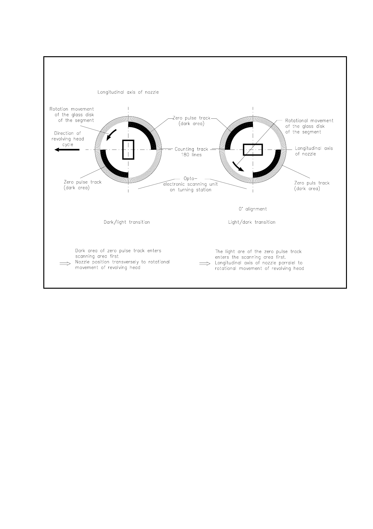
9.6.3.2 Opto-Electronic Scanner Unit of dp1 and dp2
The position of the nozzle is determined by opto-electronic scanning at each turning station. It consists of 5
photo diodes at the transmitting end and 5 photo transistors at the receiving end. The glass disk of the seg-
ment rotates with its zero pulse track between them in order to determine the position of the nozzle and also
with a 180-line counter track at the edge of the glass disk in order to turn the component precisely into the
required position. The signals from the photo transistors supply in each case two track signals for tracks A and
B and one signal for the zero pulse.
SIPLACE 80S/F/G Service Manual 9 Revolver Head
Edition 04/97
9 - 55
Fig. 9.6.9 Position of the nozzle longitudinal axis with respect to the direction of revolver head movement
These analog signals are amplified with the amplifier board on the encoder housing front (see Fig. 9.6.4) and
multiplied on the quintuple board and converted into square-wave signals for the purposes of evaluation in the
axis controllers. The track signals are illustrated in Fig. 9.6.15.
Fig. 9.6.10 shows the position of the longitudinal axis of the nozzle with respect to the zero pulse track.
Depending on whether the opto-electronics registers a light-dark or dark-light transition of the zero pulse
track, the current nozzle position is detected and then the nozzle turned into the required position.
The resolution of the electronic positioning system is 10 digits per degree.