80S-15贴片机.pdf - 第224页
7 Components Table S IPLACE 80 S/F/G Servic e Manual Edition 04/97 7 - 42 7.6.9 D.C. Motor 7.6.9.1 Overview to Assist Further Fault Location: Once the faults desc ribed a bove hav e been r uled out and the motor stil l w…
SIPLACE 80 S/F/G Service Manual 7 Components Table
Edition 04/97
7 - 41
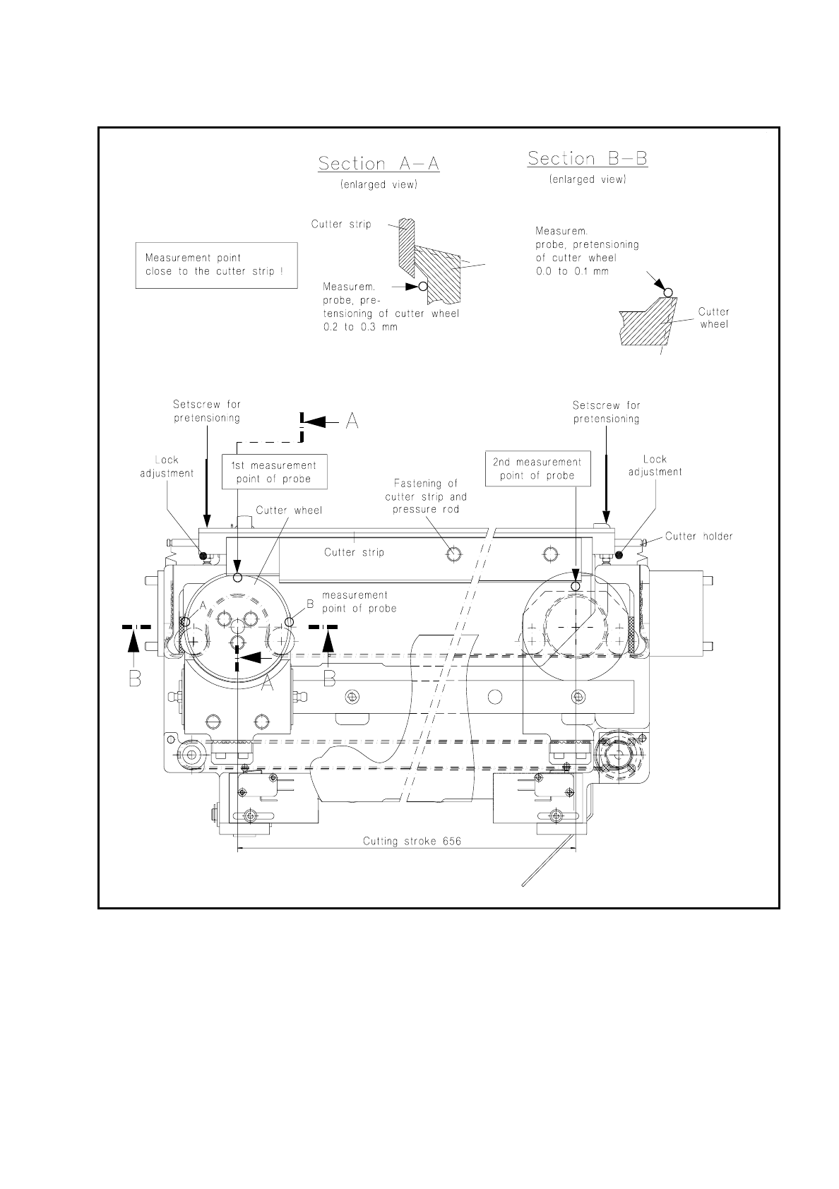
Fig. 7.6.2 Checking and replacing the cutter strip and cutter wheel; adjusting the pretensioning

7 Components Table SIPLACE 80 S/F/G Service Manual
Edition 04/97
7 - 42
7.6.9 D.C. Motor
7.6.9.1 Overview to Assist Further Fault Location:
Once the faults described above have been ruled out and the motor still will not activate, there may be
–
a defect in the d.c. motors,
–
a break in the components table interface cable Y559-W1 (plug X37
→
communications unit),
–
an interruption on the "Flap opener control" board or
–
an interruption on the processor board of the communications unit.
●
Since very little effort is required to install a replacement motor, by doing so you can quickly locate the fault
more precisely.
●
Accordingly, if the new motor will not activate, first exclude a break in the "Components table interface"
cable Y559-W1.
●
Next, and for test purposes, swap over the components changeover tables. In this way you can determine
whether the fault is ultimately caused by the communications unit (including cable Y559-W1) or the "Flap
opener control" board.
●
Proceed in detail as described below.
7.6.9.2 Replacement of the Motor Unit
●
The components changeover table has already been removed from the machine in the course of fault
location.
●
To be able to access the nut of the guide pulley on cutting unit undo the screws securing the swivel cylin-
der.
●
Undo the nut securing the guide pulley of the endless toothed belt.
●
Remove the endless toothed belt.
●
Disconnect all electric cables from the motor unit.
●
Undo the four screws at the motor unit.
●
Remove the motor unit.
●
Install new motor unit and secure it using screws.
●
Connect the electric cables to the motor unit.
●
Place the cut toothed belt around the guide pulley and the motor unit.
●
Attach the clamping connector so that the ends of the cut toothed belt are joined and clamped centrally.
●
Move the cutter wheel to the park position.
●
Tension the belt by displacing the guide pulley in the elongated hole.
●
Measure the belt tension in the center of the endless toothed belt (Setpoint value: 30 - max. 35Hz).
NOTE:
Repeat the two aforementioned procedures until the belt is tensioned correctly.
●
Fasten the swivel cylinder.
●
Screw the motor onto the support (4 fillister head screws M3x5).
SIPLACE 80 S/F/G Service Manual 7 Components Table
Edition 04/97
7 - 43
●
Plug the push-on receptacles including capacitor onto the motor connections, making sure the polarity is
correct (see Fig. 7.6.3).
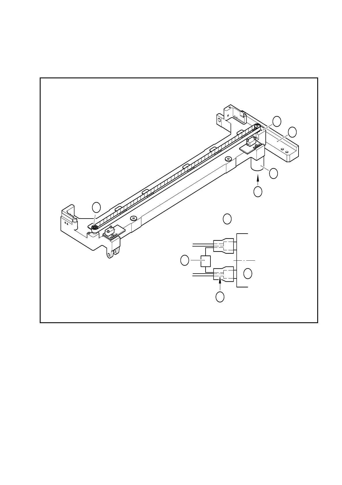
Fig. 7.6.3 Replacing the motor or capacitor
Key to Fig. 7.6.3
1 Machine base
2 D.C. gear motor
3 Fixing screws for the gear motor, 4 M3x5 fillister head screws
4 Deflection pulley of the cut toothed belt
5 Connection cable Y637-W2
6 Ceramic capacitor 10nF / 100V
+ pole: cable colors white, brown, green
- pole: cable colors yellow, grey, pink
A Electrical connection of the gear motor
A
4
3
1
2
A
6
2
5