80S-15贴片机.pdf - 第426页
9 Revolver Head SIPLACE 80S/F/G Service Manual Edition 04/97 9 - 142 Fig. 9.19.1 Screwdriver 2 Key to Fig . 9.19.1 ● Loosen th e two M 1 .6 x 3 fil lister head s crews for fixin g the DC moto r (see ite m 1 in Fig. 9.19.…

SIPLACE 80S/F/G Service Manual 9 Revolver Head
Edition 04/97
9 - 141
9.19 Service work on screwdriver 2
9.19.1 Tools, equipment and consumables
9.19.2 Spare parts
9.19.3 Screwdriver 2 - replacing the motor
●
Dismantle the encoder housing as described in Section 9.13 on page 9 - 103.
●
Loosen the two M 2.5 x 5 countersunk screws for fixing the link (see item 10 in Fig. 9.19.1).
●
Carefully remove the link from the parallel pins on the lifting carriage housing (see item 9 in Fig. 9.19.1).
●
Loosen the two countersunk head screws for fixing cover plate (see item 3a in Fig. 9.19.1) and stop (see
item 3 in Fig. 9.19.1).
●
Loosen the two M 1.4 x 5 fillister head screws on toothed wheel 1 (see item 2 in Fig. 9.19.1) and pull the
toothed wheel off the motor shaft.
●
Strip the heat-shrink sleeves from the electrical connections of the DC motor (see item 1 in Fig. 9.19.1) and
unsolder the cable.
From item number
Set of screwdrivers
Set of hexagon socket-head screwdrivers
Soldering iron
Hot air gun
Scribing iron
0.2 mm feeler gauge
Unimoly GL82 lubricating grease/ 25 g
00313490-01
Ethyl alcohol
Shrink-fit hose
Number in
Fig. 9.19.1.
From item number
DC motor, complete
1 00323190S01
Stop
3 00201268-06
Cover plate
3a 00320825-01
Toothed wheel 1 - reject
2 00318184-02
5 x 8 x 2.5 MF 85 ZZS miniature ball bearing
4 00303950S01
FS 8 x 10 spring washer
5 00201299-01
Toothed wheel 2 - reject
6 00318183S02
BERO 3RG4603-2AB00/3.0 MM/SN = 0.6 MM/1S
7 00303945-01
Toothed wheel holder
8 00201261-03
9 Revolver Head SIPLACE 80S/F/G Service Manual
Edition 04/97
9 - 142
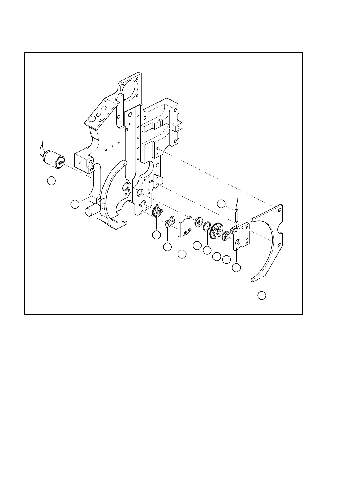
Fig. 9.19.1 Screwdriver 2
Key to Fig. 9.19.1
●
Loosen the two M 1.6 x 3 fillister head screws for fixing the DC motor (see item 1 in Fig. 9.19.1).
●
Pull the DC motor out from the back.
●
Insert the new DC motor and fix in place.
1 Motor-DC, complete
2 Toothed wheel 1 - ’reject’
3 Stop 3a Cover plate
4 5 x 8 x 2.5 MF85 ZZS miniature ball bearing
5 FS 8 x 10 spring washer
6 Toothed wheel 2 - ’reject’
7 3RG4603-2AB00/3.0 mm/SN = 0.6 mm/1S BERO
8 Toothed wheel holder
9 Lifting carriage housing
10 Link
1
10
7
8
4
4
5
6
9
3a
3
2
SIPLACE 80S/F/G Service Manual 9 Revolver Head
Edition 04/97
9 - 143
●
Push new heat-shrink sleeves over the motor cable.
●
Solder the cable to the DC motor. Check that the polarity of the terminals is correct:
Cable colors: red = +, black =
−
●
Carefully shrink on the heat-shrink sleeves using the hot air gun.
●
Lightly grease the teeth of toothed wheel 1 with Unimoly GL82.
●
Fix toothed wheel 1 in place.
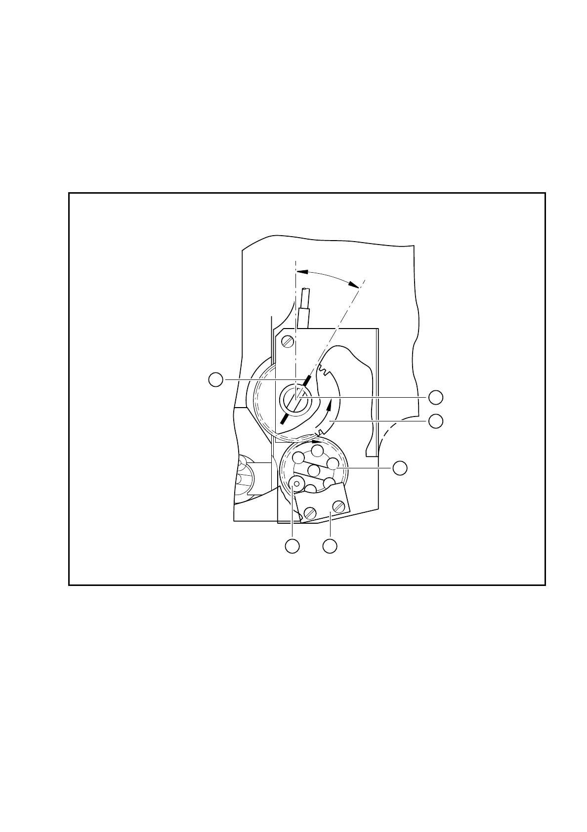
Check the position of the screwdriver blade with respect to toothed wheel 1 against the following diagram:
Fig. 9.19.2 Position of toothed wheel 1 and the screwdriver blade during reassembly
Key to Fig. 9.19.2
1Stop
2 Toothed wheel 1
3 BERO trigger surface: on the right
4 Screwdriver blade is in the 30° position
5 30° identified by mark
6 The small stop wheel of toothed wheel 1 is against the stop
30°
16
2
3
4
5