80S-15贴片机.pdf - 第213页
SIPLACE 80 S/ F/G Service M anual 7 Components Table Edition 04/97 7 - 31 7.5.2. 6 Setti ng the Vibrat ion I ntensit y A prec ondition for ca rrying o ut adj ustment i s that th e bas ic cal ibratio n of the vibrator y f…
7 Components Table SIPLACE 80 S/F/G Service Manual
Edition 04/97
7 - 30
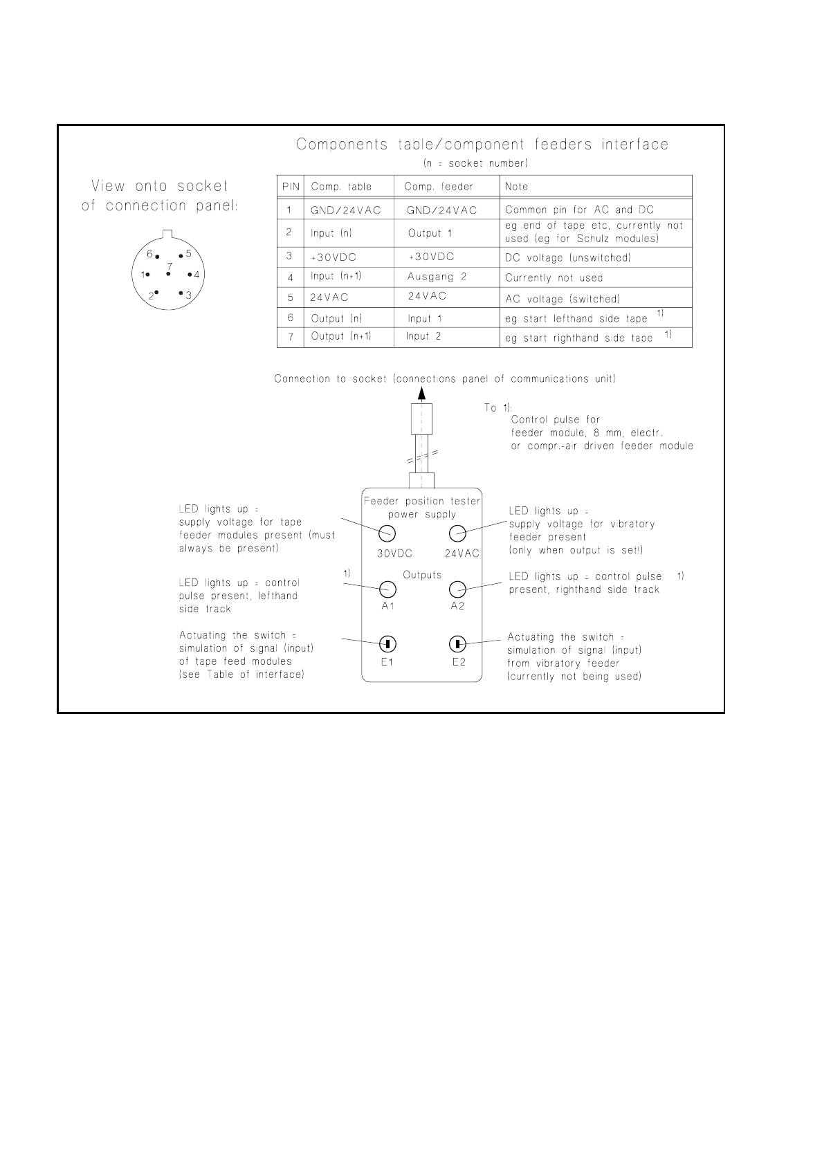
Fig. 7.5.2 Feeder position tester and assignments of the sockets on the connections panel
●
If no voltage or output is detected during this testing at any one socket or at all of them, replace the com-
munications unit as described in the corresponding section below.
●
If voltage and / or the signal are present at the socket, this indicates a fault within the feeder module or in
the connecting cable of the module.
●
With vibratory feeders, before making any fault correction in the module check first the setting of the poten-
tiometer on the connections panel (see section 7.5.2.6 on page 7 - 31).

SIPLACE 80 S/F/G Service Manual 7 Components Table
Edition 04/97
7 - 31
7.5.2.6 Setting the Vibration Intensity
A precondition for carrying out adjustment is that the basic calibration of the vibratory feeder has already been
carried out and that there are components on the feeder.
●
Activate the vibrator (vibratory feeder) of the corresponding track:
–
With the station software loaded, select:
menu "Component feeding"
→
"Location"
→
"Vibrate linear conveyor"
→
Return. The output for the
vibratory feeder will remain set until you cancel the function "Vibrate linear conveyor" (toggle function).
–
With SITEST program from version 1.64 loaded, select: "Functions"
→
"BE table"
→
"Single function"
→
"Adr. or track"
→
"Lin. feeder"
→
input the vibration period
→
Return.
●
While the vibration intensity is being activated, turn the corresponding potentiometer rotary button (see
Fig. 7.5.1) until the component is conveyed forward briskly but does not "jump" in the track.
7.5.2.7 Replacing the Communications Unit
●
Complete the SITEST program
DANGER
QQQ
Switch off the machine at the main switch and disconnect it from the power supply.
●
Open the protective cover and pull the protective cover at the components feed point upwards and away.
●
If necessary, cut the tapes at the front end of the module and pull the remaining tape with components
backwards and out. Roll the tape back onto the reels. The tape reels remain in place in the compartments
as their allocation to the track must be retained.
NOTE:
If you have already unintentionally removed tape reels / feeder modules, restore their original arrange-
ment as described in the User’s Manual, Section 9, under "Components tables".
●
Pull out all plugs of the feeder modules which are plugged into the connections panel of the communica-
tions unit. The feeder modules will remain in place unchanged.
●
Undo the mounting of the front panel of the communications unit (6 recessed head screws M3) and pull the
unit front panel including boards forwards and out a little:
●
Undo the plug connections of the cables coming in from the back and
●
the screws fastening the housing to the frame (4 socket-head cap screws M4, see Fig. 7.5.1).
●
Remove the communications unit out of the frame from the front.
●
Install the new communications unit in the reverse sequence of operations. Before refitting the front panel
make sure all plug connections are firmly seated and the back-up battery (see Fig. 7.5.1) is in place.
●
Plug all feeder modules into their associated sockets. Insert all tapes into the modules.
●
Reconnect the plug connections of the components changeover table in the machine base, connect the
machine to the power supply, switch the machine on.

7 Components Table SIPLACE 80 S/F/G Service Manual
Edition 04/97
7 - 32
●
Check the activation of the LED for the 24 VAC voltage on the connections panel.
●
Check the functioning of the new communications unit using the SITEST program or by component pick-
up from this location. After this, start the placement sequence.