80S-15贴片机.pdf - 第175页
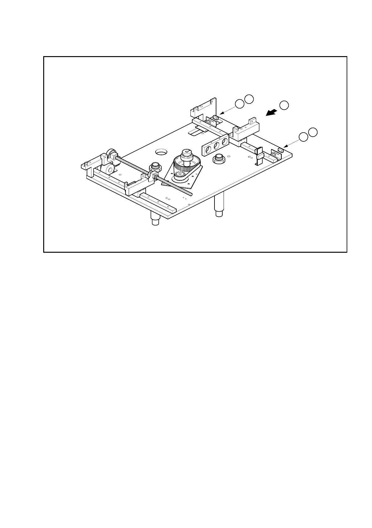
SIPLACE 80 S/ F/G Service M anual 6 PCB Handling Edition 01/96 6 - 39 Fig. 6. 8.2 Replacing limit switches Key to Fi g. 6.8.2 1 Li mit sw itch, maxi mum wi dt h 2 Limit swi tch, minimu m width T Direc tion of P CB trans …

6 PCB Handling SIPLACE 80 S/F/G Service Manual
Edition 01/96
6 - 38
●
Tilt the synchronizing disk a little and change the toothed belt (B).
●
Fasten the pressure flange.
●
Carry out a function test as specified in the adjustment instructions.
●
Fit the lifting table back as described in Section 6.7.2, Page 6 - 32.
6.8.2 Replacing the width adjustment stepping motor
Spare parts, auxiliary materials and equipment
Width adjustment stepping motor, Item No. 00300592-01
●
Remove the Synchroflex toothed belt as described in Section 6.7.1, Page 6 - 31, steps (A) and (B).
●
Undo the four M3 hexagon socket screws of the motor mounting (C).
●
Disconnect the motor connection wires from terminals 7, 8, 9 and 10 of terminal strip X1rn of the ’Width
adjustment stepping motor A6’ conversion unit.
●
Pull the connection cable carefully out of the cable ducts.
●
Connect the cable ends of the new motor to the terminal strip and check against the circuit diagrams folder
to make sure you have connected the motor up correctly.
●
Insert the connection cable in the cable ducts.
●
Mount the width adjustment motor.
●
Fit the synchronizing toothed belt.
●
Carry out a function test as specified in the adjustment instructions.
●
Fit the lifting table as described in Section 6.7.2, Page 6 - 32.
6.8.3 Replacing the width adjustment limit switches
Spare parts, auxiliary materials and equipment
Set of width adjustment limit switches, Item No. 00300594-04
NOTE
OOO
You should also comply with the safety instructions in Chapter 1 and Section 6.7.1, Page 6 - 31.
●
Remove the lifting table as described in Section 6.7.1, Page 6 - 31.
●
Use a pin to mark the precise position of the microswitch and unsolder the connection wires. Remove the
limit switch (A).
●
Fit the new limit switch at the place marked and resolder the connection wires.
●
Carry out a function test as specified in the adjustment instructions.
SIPLACE 80 S/F/G Service Manual 6 PCB Handling
Edition 01/96
6 - 39
Fig. 6.8.2 Replacing limit switches
Key to Fig. 6.8.2
1 Limit switch, maximum width
2 Limit switch, minimum width
T Direction of PCB transport
T
A
1
A
2

6 PCB Handling SIPLACE 80 S/F/G Service Manual
Edition 01/96
6 - 40