80S-15贴片机.pdf - 第396页
9 Revolver Head SIPLACE 80S/F/G Service Manual Edition 04/97 9 - 112 Fig. 9.15.1 Segment V I I, E 6.1 Key to Fig . 9.15.1 1 S egment bo dy 8 O-ring, 2 x 1, NBR 5 5 2 S ealing p iston 9 Sleeve, complete , version I I 3 R …

SIPLACE 80S/F/G Service Manual 9 Revolver Head
Edition 04/97
9 - 111
9.15 Service work on the segment, version II, E 6.x
9.15.1 Tools, equipment and consumables
9.15.2 Spare parts
From item number
Tool for replacing sleeves and pushers, version II, consisting of:
screwdriver for sleeves, torque insert for ring nuts,
torque wrench
00319153-01
SIPLACE segment changing device, version II
00305897-02
Set of watchmaker’s screwdrivers
Segment case
00302217-01
Brush
Lint-free cloth
Segment cleaning cloth
00315253-01
Ethyl alcohol
Number in
Fig. 9.15.1.
From item number
Repair kit for segments, version II, consisting of:
00315909-01
1 cassette for M10/34 ABS SW scale disks
5 00066059-01
12 sleeves,complete, version II
9 00310319S02
12 deep-groove ball bearings 14 * 9 * 3 UL 914 X
10 00304142-01
Sealing piston, complete, version II (05.94)
2 00315245S01
Ring nut
3 00301521-03
Friction wheel
4 00201520S02
Cam (version II, spring-mounted ball latching mecha-
nism)
7 00315520-02
2 x 1 NBR 55 O-ring
8 00315630-01
Prestressing plate
11 00201522-03
Deep-groove ball bearings 8 * 12 * 2.5 UL 812 X
12 00304151-01
Spring washer FS 10 x 12
13 00201553-01
Spacer ring
14 00201517S02
9 Revolver Head SIPLACE 80S/F/G Service Manual
Edition 04/97
9 - 112
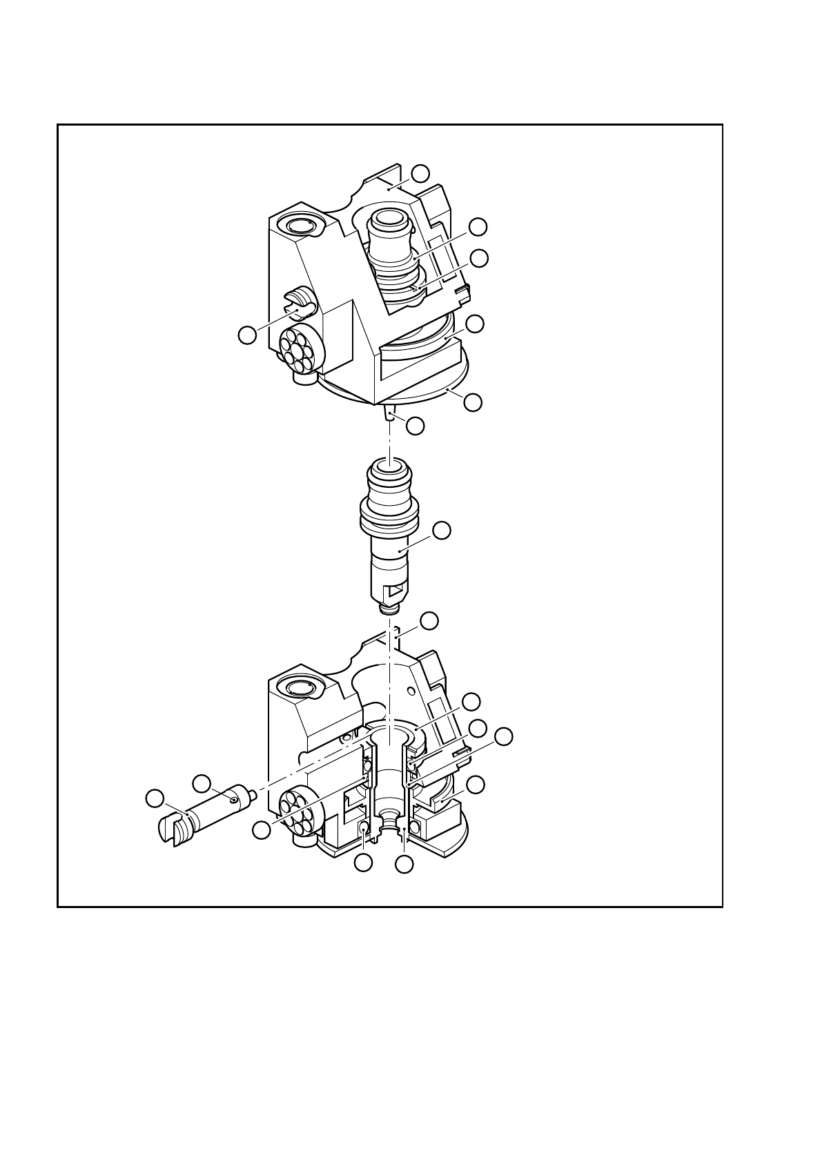
Fig. 9.15.1 Segment V II, E 6.1
Key to Fig. 9.15.1
1 Segment body 8 O-ring, 2 x 1, NBR 55
2 Sealing piston 9 Sleeve, complete, version II
3 Ring nut 10 Deep-groove ball bearings 14 * 9 * 3 UL
914 X
4 Friction wheel 11 Prestressing plate
5 Scale disc for the sleeve 12 Deep-groove ball bearings 8 * 12 * 2.5
UL 812 X
14
E6.1
E6.1
2
3
4
5
6
7
1
2
3
4
10
9
7
8
11
13
12

SIPLACE 80S/F/G Service Manual 9 Revolver Head
Edition 04/97
9 - 113
9.15.3 Removing segments
DANGER
OOO
Switch the placement machine off at the main switch and disconnect from the power supply.
●
Remove the segment using the segment changing device.
PLEASE NOTE:
If you are removing several segments, note the order of the segments and from which star position you
removed the segments. In this way, you will ensure that the configuration will be correct when you refit the
segments.
●
Place the segments in the segment case.
9.15.4 Removing the nozzle
●
Turn the cam shaft so that the sealing piston is fully retracted.
The slot in the cam shaft must be horizontal.
●
Remove the nozzle.
9.15.5 Dismantling the sealing piston
●
Pull the cam shaft out approximately 3 mm until the sealing piston can be pulled out of the sleeve.
9.15.6 Dismantling the sleeve
●
Place the segment on a clean surface.
●
Take the screwdriver for the sleeve from the sleeve changing tool (see Fig. 9.15.2) and introduce it into the
hole in the sleeve from the nozzle side.
Ensure that the parallel pin of the screwdriver engages in the groove in the nozzle seat.
●
Place the torque insert for the ring nuts (see Fig. 9.15.2) on the ring nut.
●
Use the screwdriver to prevent the sleeve turning when you unscrew the ring nut.
●
Pull the sleeve out of the segment. Be careful not to lose the spring washer, the spacer ring and the upper
deep-groove ball bearing.
6 Nozzle 13 Spring washer FS 10 x 12
7 Cam, V II 14 Spacer ring