80S-15贴片机.pdf - 第391页
SIPLACE 80S/F/G Service Manual 9 Revolver Head Edition 04/97 9 - 107 9.14 Dismantlin g the hous ing cover 9.14.1 Tools, equipm ent and consum ables 9.14.2 Dismantling the PCB camera DANGER OOO Switch t he plac ement mac …

9 Revolver Head SIPLACE 80S/F/G Service Manual
Edition 04/97
9 - 106

SIPLACE 80S/F/G Service Manual 9 Revolver Head
Edition 04/97
9 - 107
9.14 Dismantling the housing cover
9.14.1 Tools, equipment and consumables
9.14.2 Dismantling the PCB camera
DANGER
OOO
Switch the placement machine off at the main switch and disconnect from the power supply.
●
Remove connector X1 of cable Y0577 (point 5 in Fig. 9.14.1) from terminal X1 on board Y0029.
●
Remove connector X3 (point 6 in Fig. 9.14.1) of the lens system lighting cable from terminal X2 on board
Y0029.
●
Remove connector X1 of the PCB camera cable Y0597 (see item 2 in Fig. 9.14.1) from the PCB camera
amplifier.
●
Loosen the cable clip (see item 3 in Fig. 9.14.1).
●
Dismantle the red retaining bracket.
●
Loosen the 4 M3 hexagon socket-head screws (see item 6 in Fig. 9.14.2) for fixing the PCB camera holder
(see item 5 in Fig. 9.14.2).
From item number
Set of hexagon socket-head screwdrivers
Diagonal cutter
Cable ties
SITEST program
9 Revolver Head SIPLACE 80S/F/G Service Manual
Edition 04/97
9 - 108
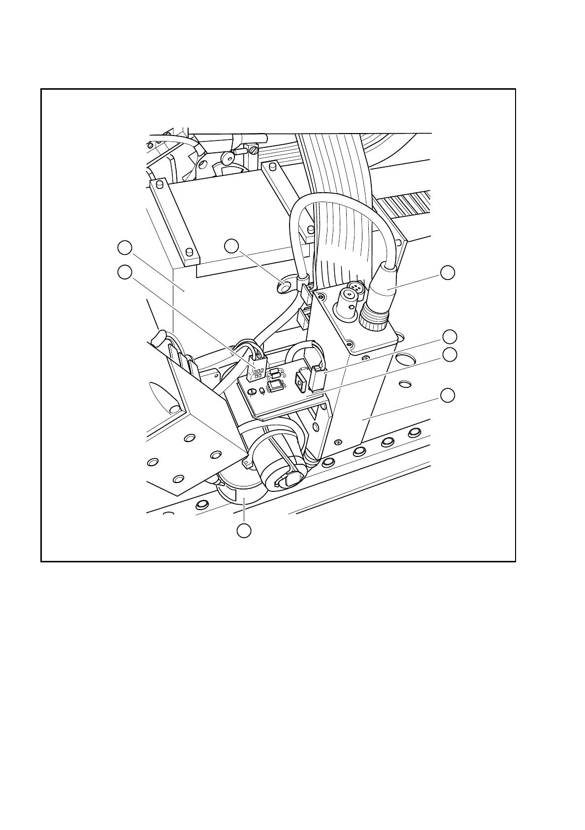
Fig. 9.14.1 Plug-in connections on the PCB camera
Key to Fig. 9.14.1
1 PCB camera amplifier 5 Connector X1 on cable Y0577
2 Connector X1 on PCB camera cable Y0597 6 Connector X2 on the cable for the lens system light-
ing
3 Cable clip for the PCB camera cable 7 Illumination control for PCB camera Y0029
4 Cover 8 PCB optical system and PCB illumination
8
2
5
4
3
6
1
7