80S-15贴片机.pdf - 第173页
SIPLACE 80 S/ F/G Service M anual 6 PCB Handling Edition 01/96 6 - 37 6.8 Width Adjustment 6.8.1 Replacing toothed belts Spare parts, auxiliary materi als and equipment Synchrof lex to othed belt 10T2. 5/230, Item N o. 0…
6 PCB Handling SIPLACE 80 S/F/G Service Manual
Edition 01/96
6 - 36
6.7.5 Replacing the lifting table limit switches
Spare parts, auxiliary materials and equipment
Lifting table limit switch, Item No. 00317892-03
NOTE
OOO
You should also comply with the safety instructions in Chapter 1 and Section 6.7.1, Page 6 - 31.
●
Remove the lifting table as described in Section 6.7.1, Page 6 - 31.
Fig. 6.7.4 Replacing the lifting table limit switch
Key to Fig. 6.7.4
●
Use a pin to mark the precise position of the limit switch as installed (A).
●
Unsolder the connection wires.
●
Remove the limit switch and fit the new one at the place marked.
●
Solder the connection wires on.
●
Install the lifting table as described in Section 6.7.2, Page 6 - 32.
1 ’Lifting table at bottom’ limit switch 2 ’Lifting table at top’ limit switch
T Direction of board transport
1
2
A
T
SIPLACE 80 S/F/G Service Manual 6 PCB Handling
Edition 01/96
6 - 37
6.8 Width Adjustment
6.8.1 Replacing toothed belts
Spare parts, auxiliary materials and equipment
Synchroflex toothed belt 10T2.5/230, Item No. 00317711-01
SITEST program
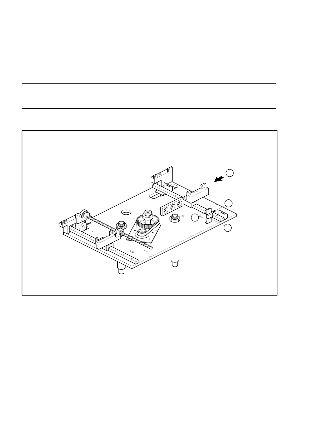
Fig. 6.8.1 Width adjustment
Key to Fig. 6.8.1
NOTE
OOO
You should also comply with the safety instructions in Chapter 1 and Section 6.7.1, Page 6 - 31.
●
Remove the lifting table as described in Section 6.7.1, Page 6 - 31.
●
Undo the three M3 x 6 countersunk screws which fasten the pressure flange (A) to the synchronizing disk.
1 Synchroflex toothed belt 10T2.5/230 2 Synchronizing disk 2 Al T2.5/Z64
3 Width adjustment stepping motor 4 Pressure flange
T Direction of board transport
1
2
T
B
3
C
4
A

6 PCB Handling SIPLACE 80 S/F/G Service Manual
Edition 01/96
6 - 38
●
Tilt the synchronizing disk a little and change the toothed belt (B).
●
Fasten the pressure flange.
●
Carry out a function test as specified in the adjustment instructions.
●
Fit the lifting table back as described in Section 6.7.2, Page 6 - 32.
6.8.2 Replacing the width adjustment stepping motor
Spare parts, auxiliary materials and equipment
Width adjustment stepping motor, Item No. 00300592-01
●
Remove the Synchroflex toothed belt as described in Section 6.7.1, Page 6 - 31, steps (A) and (B).
●
Undo the four M3 hexagon socket screws of the motor mounting (C).
●
Disconnect the motor connection wires from terminals 7, 8, 9 and 10 of terminal strip X1rn of the ’Width
adjustment stepping motor A6’ conversion unit.
●
Pull the connection cable carefully out of the cable ducts.
●
Connect the cable ends of the new motor to the terminal strip and check against the circuit diagrams folder
to make sure you have connected the motor up correctly.
●
Insert the connection cable in the cable ducts.
●
Mount the width adjustment motor.
●
Fit the synchronizing toothed belt.
●
Carry out a function test as specified in the adjustment instructions.
●
Fit the lifting table as described in Section 6.7.2, Page 6 - 32.
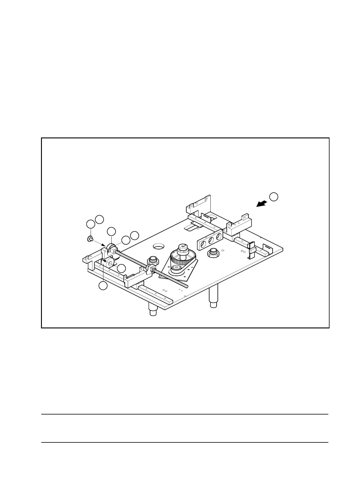
6.8.3 Replacing the width adjustment limit switches
Spare parts, auxiliary materials and equipment
Set of width adjustment limit switches, Item No. 00300594-04
NOTE
OOO
You should also comply with the safety instructions in Chapter 1 and Section 6.7.1, Page 6 - 31.
●
Remove the lifting table as described in Section 6.7.1, Page 6 - 31.
●
Use a pin to mark the precise position of the microswitch and unsolder the connection wires. Remove the
limit switch (A).
●
Fit the new limit switch at the place marked and resolder the connection wires.
●
Carry out a function test as specified in the adjustment instructions.