80S-15贴片机.pdf - 第232页
7 Components Table S IPLACE 80 S/F/G Servic e Manual Edition 04/97 7 - 50 ● Open the s hut-off v alve in the co mpressed a ir supp ly line and switc h the m achine o n at the main switc h. ● Check th e figur es sho wn by…

SIPLACE 80 S/F/G Service Manual 7 Components Table
Edition 04/97
7 - 49
7.6.12 Swivel Mechanism
–
If the pressure rod is not pressed strongly enough against the spring bows or the empty tape during the
cutting process (see Fig. 7.6.8), the tapes may slip over one another during cutting (tape jam, poor cuts).
–
If the pressure rod does not swing out far enough when the tape cycles on, the tapes may not slide down
the empty tape channel which will also lead to a tape jam.
A fault in the swivel movement can indicate a fault in the 5.6 bar compressed air branch, in the solenoid valve,
in the compressed air cylinder, or incorrect adjustment of the restrictor valves or fatigued tension springs.
–
Detailed information on the electrical and pneumatic systems and on the functional sequence will be found
under "Overview" in section 7.1.4 "Empty Tape Cutting Device".
7.6.12.1 Checking the Swivel Movement
●
Please observe the DANGER notes in section 7.6.2 on page 7 - 34, concerning working with the SITEST
program
(danger of physical injury!)
.
●
Select "Abort placement" and load the SITEST program.
●
If necessary, have on hand the detailed functional sequence described in section 7.1.4 "Empty Tape Cut-
ting Device".
●
Select "BE table"
→
"Single function"
→
"Tape cutter".
●
At the same time check by eye the empty tapes and the swivel movement of the pressure rod.
–
If the pressure rod does not swing far enough in or out, check the compressed air branch as described
below.
–
If the pressure rod swings in too slowly or bounces as it swings in or out, adjust the supply or exhaust
air restrictor valve (see "Concluding work").
7.6.12.2 Checking the Compressed Air Branch
●
Remove the compressed air unit cover from the machine base (undo 2 special socket-head cap screws
M3).
●
Check the threaded hose connections at the solenoid valve of the tape cutting unit (see Fig. 7.6.7) and at
the compressed air unit (see Fig. 7.6.6) for leaks.
●
If these screwed connections are okay, proceed as follows:
DANGER
QQQ
Switch the machine off at the main switch and disconnect it from the power supply.
NOTE
OOO
Switch the compressed air supply line at the shut-off valve of the compressed air unit (see Fig. 7.6.6).
●
Check the compressed air hose between the compressed air unit and the solenoid valve:
–
If the compressed air hose pinched, replace it. Replace all of the cable lacings.
7 Components Table SIPLACE 80 S/F/G Service Manual
Edition 04/97
7 - 50
●
Open the shut-off valve in the compressed air supply line and switch the machine on at the main
switch.
●
Check the figures shown by the pressure gauges and refit the cover over the compressed air unit
at the machine base (2 special socket-head cap screws M3).
–
If there is still no fault, the compressed air cylinder or the solenoid valve could be defective. Continue
work with the next section.
NOTE:
The + 30 VDC electric circuit and the activation of the solenoid valve were already checked earlier in sec-
tion 7.6.2.1.
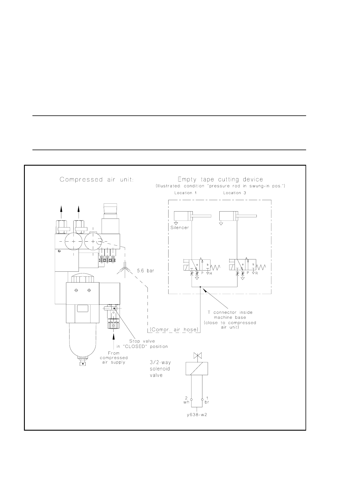
Fig. 7.6.6 Compressed air connection of the tape cutting units and electrical connection of the solenoid valve (cable Y637-W1/W2)

SIPLACE 80 S/F/G Service Manual 7 Components Table
Edition 04/97
7 - 51
7.6.12.3 Replacing the Solenoid Valve or Compressed Air Cylinder
For the following work the tape cutting unit can remain installed in the machine.
●
In the course of fault location (see above) the machine has already been switched off and the components
changeover table removed.
●
For detailed information on the location, removal and installation of the solenoid valve and, if applicable, of
the compressed air cylinder, refer to Fig. 7.6.7.
●
When installing or replacing the solenoid valve make sure that the regulators are in their correct assigned
positions:
exhaust air restrictor should be at the compressed air cylinder, the restrictor valve at the supply connection
of the solenoid valve, as shown in Fig. 7.6.6 and Fig. 7.6.7. The Item Nos. of the regulator will be found
under "Spare Parts".
NOTE
The 3/2-way solenoid valve is an alternating current solenoid valve which is connected in parallel with the
motor and operated with 22V. It is reset by spring power.
●
After replacing the compressed air cylinder, insert the shaft circlips of the cylinder and fork-joint pivot into
the annular groove on the shaft. Adjust the swivel movement of the pressure rod as described below.
●
Carry out all operations described in section 7.6.15 „Concluding Work“ on page 7 - 55.
7.6.12.4 Adjusting the Swivel Movement, Replacing the Tension Springs
If the swivel movement is faulty, once you have excluded a fault in the compressed air branch (see above)
check the setting and the tension springs as follows:
●
In the course of fault location (see above) the machine has already been switched off and the components
changeover table removed.
●
Swivel movement of the pressure rod: correct the swivel movement by making the corresponding change
in the position of the fork head on the plunger rod (see Fig. 7.6.7):
●
When slackening off the lock nut (SW17) hold the fork head stationary with your second open-ended
spanner (SW17), and adjust the swivel movement to dimension 11 +1 mm (see Fig. 7.6.7).
●
Lock the fork head into this position.
●
Replacement of the tension springs: With the tape cutting unit installed, it is hard to get at the lefthand ten-
sion spring (see Fig. 7.6.7). For this reason, you should remove the empty tape cutting unit from the
machine base as described in the section 7.6.6 "Checking and Replacing the Cutter Wheel and Cutter
Strip".
●
Detach the two tension springs on the left and right of the tape cutting unit (see Fig. 7.6.7 or Fig. 7.6.4)
and fit the new tension springs into the annular groove of the spring attachment pins.
●
Reinstall the tape cutting unit, aligning it symmetrically to the empty tape channel (see below, section
7.6.14 "Fitting and Aligning the Empty Tape Cutting Unit and Empty Tape Channel").
●
Carry out all steps described in "Concluding work". In this section there is a description of checking and
adjusting the swivelling speed (inward and outward movements).