80S-15贴片机.pdf - 第393页
SIPLACE 80S/F/G Service Manual 9 Revolver Head Edition 04/97 9 - 109 Fig. 9.14.2 Fixing screws on the PCB camera and housing cover Key to F ig. 9 .14.2 ● Loosen t he two M3 fixing s crews (see it em 8 in F ig. 9.14.2) fo…
9 Revolver Head SIPLACE 80S/F/G Service Manual
Edition 04/97
9 - 108
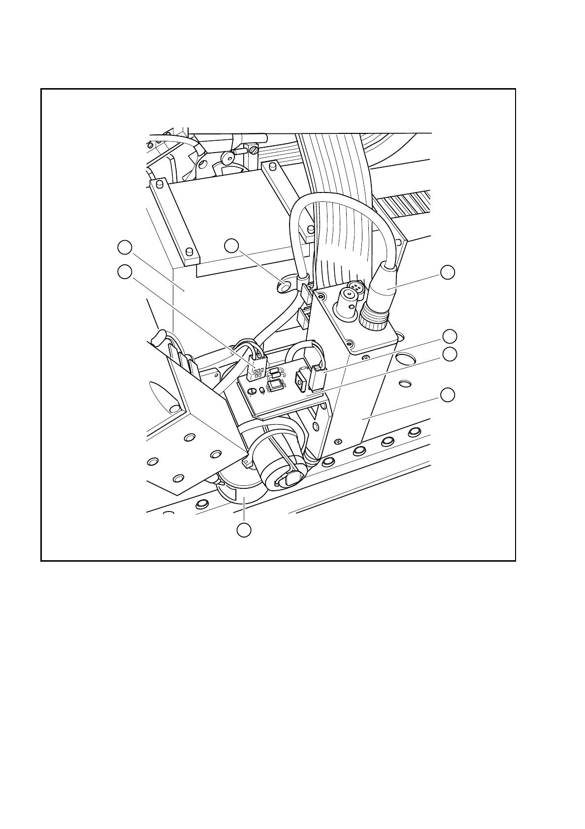
Fig. 9.14.1 Plug-in connections on the PCB camera
Key to Fig. 9.14.1
1 PCB camera amplifier 5 Connector X1 on cable Y0577
2 Connector X1 on PCB camera cable Y0597 6 Connector X2 on the cable for the lens system light-
ing
3 Cable clip for the PCB camera cable 7 Illumination control for PCB camera Y0029
4 Cover 8 PCB optical system and PCB illumination
8
2
5
4
3
6
1
7
SIPLACE 80S/F/G Service Manual 9 Revolver Head
Edition 04/97
9 - 109
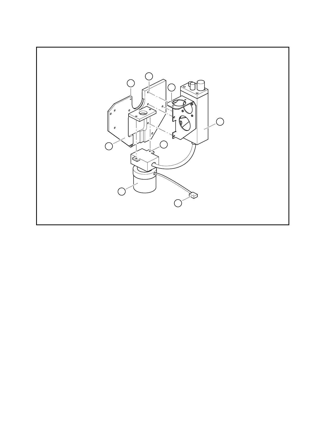
Fig. 9.14.2 Fixing screws on the PCB camera and housing cover
Key to Fig. 9.14.2
●
Loosen the two M3 fixing screws (see item 8 in Fig. 9.14.2) for the PCB optical system and remove the
PCB camera system.
9.14.3 Dismantling the housing cover
●
Loosen the 4 M3 hexagon socket-head screws (see item 7 in Fig. 9.14.2) for fixing the housing cover and
then remove the housing cover.
9.14.4 Reassembling the housing cover and PCB camera
●
Reverse the above sequence to reassemble.
●
Use the SITEST program to carry out all the calibration steps required, such as calibrating the PCB cam-
era, measuring the PCB /component offset, etc.
1 Housing cover 5 PCB camera holder
2 PCB optical system and PCB illumination 6 4 x M3 hexagon socket-head screws
3 Connector X2 on the PCB lens system cable 7 4 x M3 hexagon socket-head screws
4 PCB camera amplifier 8 2 x M3 hexagon socket-head screws
4
5
1
2
3
8
6
7

9 Revolver Head SIPLACE 80S/F/G Service Manual
Edition 04/97
9 - 110