80S-15贴片机.pdf - 第261页
SIPLACE 80S/F/G Service Manual 8 IC Head Edition 01/97 8 - 13 Key to Fi g. 8.3.1 8.3.8 Replace the Sl eeve See item 12 in F ig. 8.3.2 page 8 - 15 WARNING ∆ ! This serv icin g work may only be carrie d out by au thorize d…
8 IC Head SIPLACE 80S/F/G Service Manual
Edition 01/97
8 - 12
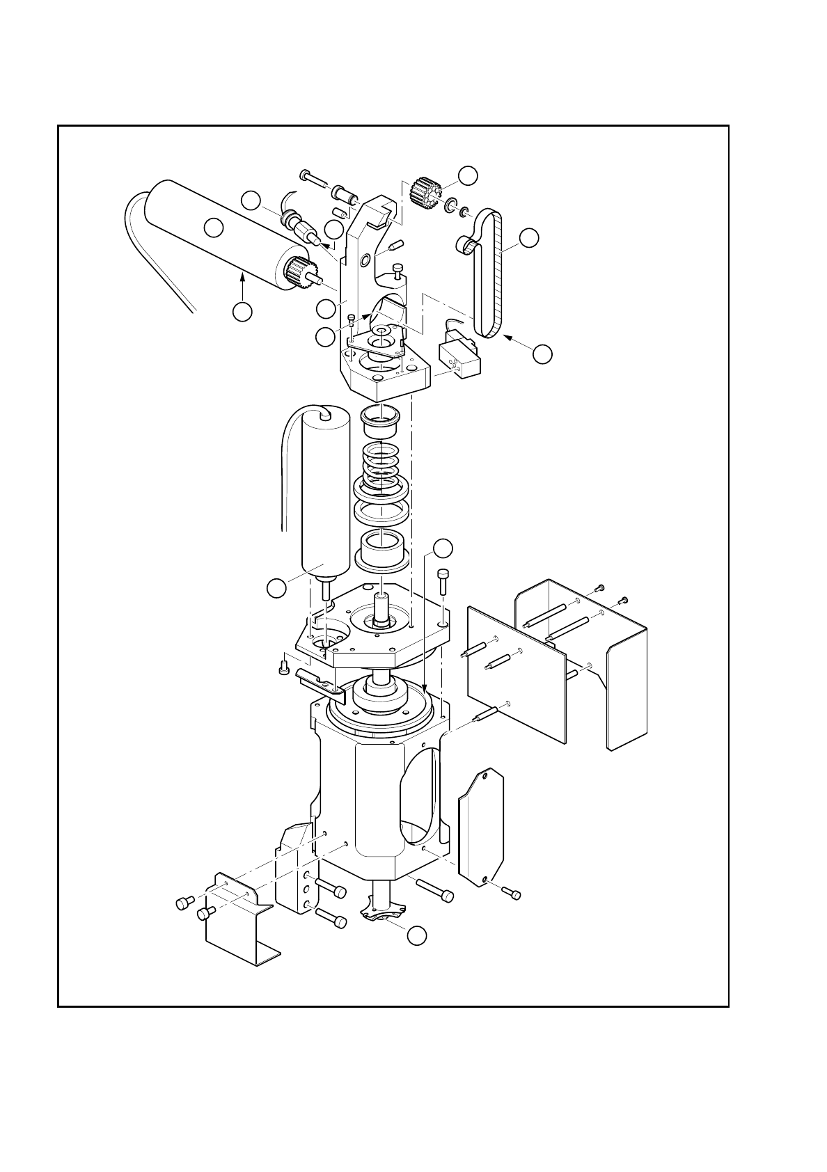
Fig. 8.3.1 Servicing work on the IC head
2
4
3
A
B
C
5
1
6
D
8
7

SIPLACE 80S/F/G Service Manual 8 IC Head
Edition 01/97
8 - 13
Key to Fig. 8.3.1
8.3.8 Replace the Sleeve
See item 12 in Fig. 8.3.2 page 8 - 15
WARNING
∆
!
This servicing work may only be carried out by authorized and trained personnel.
●
Remove the clip (item 7, Fig. 8.3.2 page 8 - 15) from the vacuum connector at the top of the sleeve.
●
Pull the vacuum hose off the vacuum connector (item 8).
●
Fix the sleeve removal mount to the lower end of the sleeve.
●
Firmly hold the sleeve and the sleeve removal mount and then loosen the hexagonal nut (item 9) at the top
of the sleeve using the size 13 open-ended spanner.
●
Using a 2 mm hexagon socket head spanner, loosen the fixing screw (item 5) on the clamping part
(item 6).
WARNING
∆
!
Before you remove the sleeve, loosen the z axis clamping device by pressing the red push-button on the
solenoid valve for the z axis clamping device (see items 4 and A, Fig. 8.2.1 page 8 - 4).
●
Pull the sleeve down and out.
To reassemble the sleeve
●
Insert the new sleeve from the bottom.
●
Check that you have released the z axis clamping device. The sleeve must move easily. If it does not
move easily, the linear ball bearing may be defective (item 1, Fig. 8.3.2 page 8 - 15). If this is the case,
return the IC head to Siemens for repair.
●
Tighten the hexagonal nut (item 9, Fig. 8.3.2 page 8 - 15) at the top of the sleeve.
1 Synchronizing disc Al 10 T2/26-0 2 Star with spring steel sheet
3 Friction wheel 4 Motor/tacho for dr axis
5 Motor/tacho for z axis 6 End position BERO
7 Synchroflex 6 T2/220 toothed belt 8 Mount
Mounting instructions
A Toothed belt tension: 190 Hz ± 5 Hz B The end face of the z motor must be flush with the mount
C Zero point correction value:
0.4 mm
=
10 digits
D The end face of the BERO must be flush with the mount

8 IC Head SIPLACE 80S/F/G Service Manual
Edition 01/97
8 - 14
●
Firmly clamp the clamping piece (item 6, Fig. 8.3.2 page 8 - 15). Ensure it does not strike against the top
or the bottom when the sleeve is moved up and down. If necessary, center the clamping piece.
●
Check again that the sleeve moves easily when the z axis clamping device is deactivated. If it does not,
the problem may be caused because the precision shaft (item 4) and the sleeve are not aligned parallel to
one another.
●
Align the two parts as follows:
–
Push the sleeve until it reaches the top position.
–
Using a 2 mm hexagon socket head spanner, loosen the screw (item 3) on the clamping piece
(item 2). The precision shaft (item 4) will align itself.
–
Tighten the hexagon socket head screw (item 3) once more. The precision shaft is now aligned.
–
Re-establish the vacuum connector.
●
Set the zero point correction values for the z axis (see section 8.3.9) and the dr axis
(see section 8.4.4, page 8 - 17).
8.3.9 Determine the Zero Point Correction for the Z Axis
PLEASE NOTE
The zero point correction is correct if the z axis is at the top mechanical stop and a value of - 10 digits for the
z position is displayed.
The zero point correction value should be between - 80 and - 120 digits. If this is not the case, you will have to
move the toothed belt slightly. The new zero point correction value can be calculated using the following
equation:
ZPC
NEW
= ACTUAL - DESIRED + ZPC
OLD
Example:
Position at the top mechanical stop = -15 (ACTUAL)
Desired value = -10 DESIRED)
ZPC
OLD
= - 110 digits
ZPC
NEW
= - 15 - (-10) + (- 110)
= - 15 + 10 - 110
= - 115