80S-15贴片机.pdf - 第464页
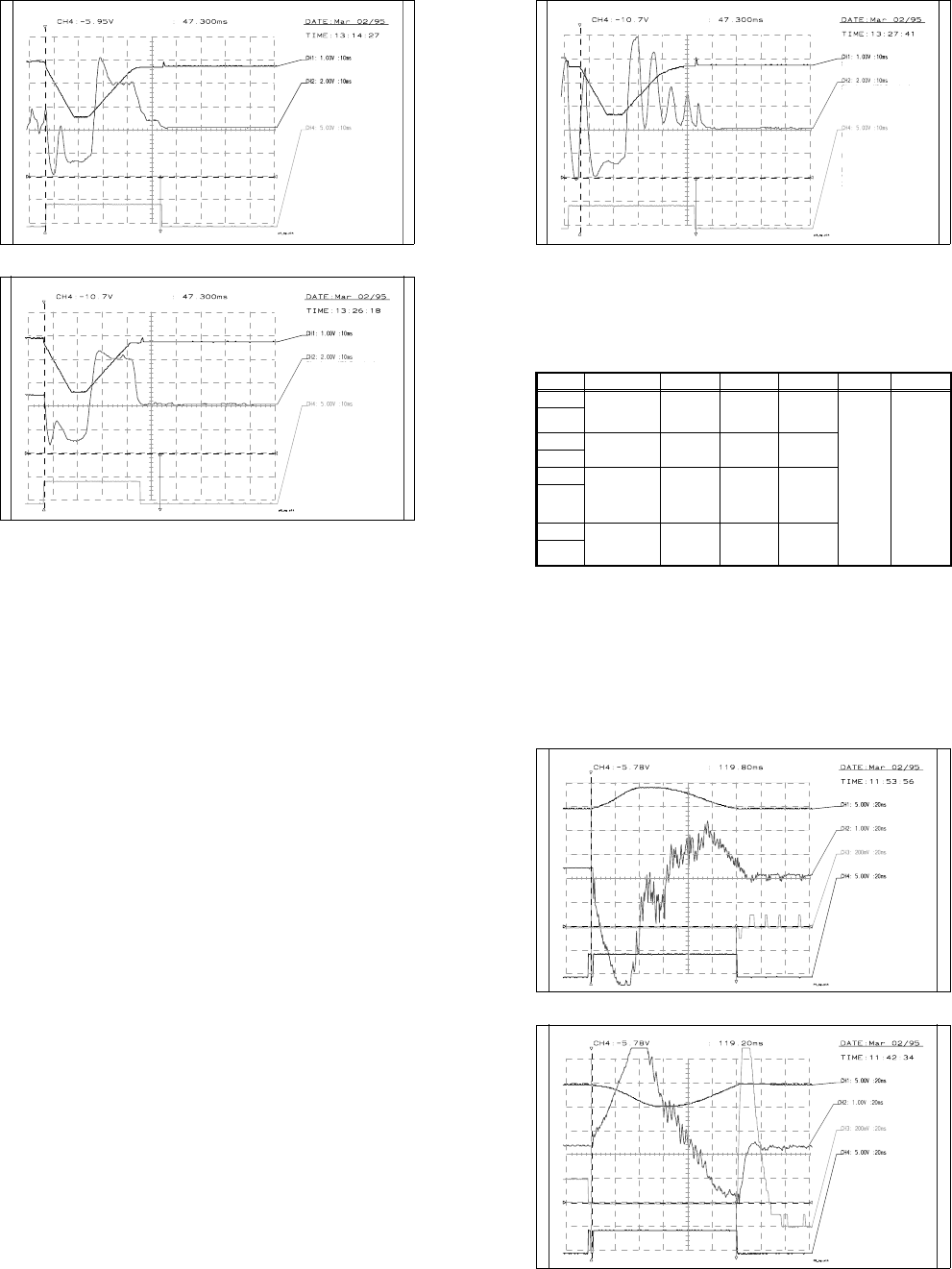
10 Si plac e G au tom atic g lue ap plic ator SIPLA CE 80 S/80 F/G Servi ce Ma nua l Ed itio n 06 /98 10 - 52 Fig. 10 .3.14 Spe ed and P gai n for th e X2 axi s (P gai n too hi gh) 10.3.6.5 X axis Genera l preparat ory w…
10 Siplace G automatic glue applicator SIPLACE 80S/80F/G Service Manual
Edition 06/98
10 - 48
Fig. 10.3.9 Diagram: Speed and P gain for z axes
Fig. 10.3.10 Diagram: P gain too low for z axes
Old calibration tool
compartment
End signal
If distance: 000000-calibration
part compartment
v: 10
acceleration: 100
deceleration: 50
time approx. 47 ms +- 2ms
Vnom value
P gain o.k.
MP6 current curve of servo board
Old calibration tool
compartment
MP6 current curve of servo
board
End signal
If distance: 000000-calibrating
path compartment
V: 10
acceleration: 100
deceleration: 50
Vnom value
P gain too low
SIPLACE 80S/80F/G Service Manual 10 Siplace G automatic glue applicator
Edition 06/98
10 - 49
Fig. 10.3.11 Diagram: P gain too high for z axes
10.3.6.4 Adjusting the dynamic behavior of the X2/Y2 axis
Preparation
● Set up glue application heads 1 and 2 with a full glue cartridge.
● Carry out a head reference run.
● Use an RC filter for the current curve (see Fig. 10.3.7).
Input Test point Signal Coupling Y deflection Trigger X deflection
CH1 Axis test box,
setpoint value
BNC socket
Setpoint
value
DC 5.00 V/Div
CH4
10% pre-
trigger
20 ms
GND
CH2
Test point 6,
servo board
Actual cur-
rent value
DC 1.00 V/Div
GND
CH3 Axis test box,
position
deviation
BNC socket
Position
deviation
DC 200 mV/Div
GND
CH4 Axis test box,
end signal
BNC socket
End signal DC 5.00 V/Div
GND
Tab. 10.3.6 Parameters for setting the oscilloscope: Adjusting the dynamic behavior of the X2/Y2 axis
Old pos. calibration tool
compartment
MP6 current curve of servo board
End signal
P gain too high
If distance: 000000- pos. cali-
bration tool compartment
v: 10
acceleration: 100
deceleration: 50
time approx 47ms +- 2 ms
Vnom value
10 Siplace G automatic glue applicator SIPLACE 80S/80F/G Service Manual
Edition 06/98
10 - 50
Adjusting the offset
● Connect the axis testing device to the axis board. Select the axis on the axis testing device (2 or 3).
● Change the MA data for adjusting the offset using the values in the table 10.3.1.
Then reference the axis.
● Use the offset potentiometer on the servo board to set the axis position to 0 ± 1 digits.
● Check: the position display must not deviate from the value 0 by more than 1 digit.
Setting the speed
● Change the MA data for setting the tacho using the values in the table 10.3.2.
Then reference the axis.
● Set the axis testing device to time measurement (set the toggle switch to -1) and set the rotary switch for
axis 0 to 1.
● Start the axis in continuous mode. Distance: 0 to 2,800 digits.
● Increase the P gain on the servo board until the axis can be easily positioned.
● Use the tacho potentiometer on the servo board to set the end message signal to 119 ms ± 5 ms.
● Check: the positioning time must be 119 ms ± 5 ms (measured with a suitable P gain).
Adjusting the P gain
● Set the MA data as for setting the tacho.
● Start the axis in continuous mode. Distance: 0 to 2,800 digits.
● Use the ratio potentiometer on the servo board to increase the P gain until a slight tendency to vibrate can
be seen on the current curve.
● Increase/reduce the P gain until the position deviation no longer dips or rises (see Fig. 10.3.13 to Fig.
10.3.14).
● Use the tacho potentiometer on the servo board to adjust the speed to 119 ms ± 5 ms.
● Check: Start the axis in continuous mode. Distance: 0 to 2,800 digits.
- The P gain must be set so that the position deviation no longer dips or rises.
- For a distance of 0 to 2,800 digits, the positioning time must be 119 ms ± 5 ms.
Checking the positioning quality in accordance with table 10.3.4
● Reset the MA data to the basic data and reference the axis.
● Start the axis in continuous mode. Distance: 0 to 2,800 digits.
● 50 ms after the end signal, the position deviation must not exceed 2 digits.
Checking the offset
See "Adjusting the offset".
Reset the MA data to basic data (see Table 10.3.4) and reference the axis (all axes).
SIPLACE 80S/80F/G Service Manual 10 Siplace G automatic glue applicator
Edition 06/98
10 - 51
Fig. 10.3.12 Speed and P gain for the X2 axis (P gain OK)
Fig. 10.3.13 Speed and P gain for the X2 axis (P gain too low)
Vnom value
MP6 current curve of servo board
Positional deviation
End signal
P gain OK
If distance: 000000-002800
v: 10 accel.: 100 decel.: 50
Vnom value
MP6 current curve of servo board
Positional deviation
End signal
P gain too low
If distance: 000000-002800
v: 10 accel.: 100 decel.: 50
10 Siplace G automatic glue applicator SIPLACE 80S/80F/G Service Manual
Edition 06/98
10 - 52
Fig. 10.3.14 Speed and P gain for the X2 axis (P gain too high)
10.3.6.5 X axis
General preparatory work
● The gluing heads and cameras must be fitted in order to set the axes.
● Use an RC filter to record the current curve and the diagnostic strip test point signal.
● Carry out a head reference sequence and an x reference sequence.
● Switch the machine on for approximately 30 minutes.
Setting the offset
Preparation:
● Connect an axis test box to the axis board and set the position display to axis number 0.
● Change the MA data for offset adjustment and reference the axis (see Table 10.3.1).
● Position the X axis at 200,000.
Setting:
● Use the offset potentiometer on the servo board to set the axis position to 200,000 ± 1 digit.
Check:
● The axis position display should not deviate from the value of 200,000 by more than 1 digit.
Vnom value
MP6 current curve of servo board
Positional deviation
End signal
P gain too high.
Current oscillating
If distance: 000000-002800
V: 10 accel.: 100 decel.: 50
SIPLACE 80S/80F/G Service Manual 10 Siplace G automatic glue applicator
Edition 06/98
10 - 53
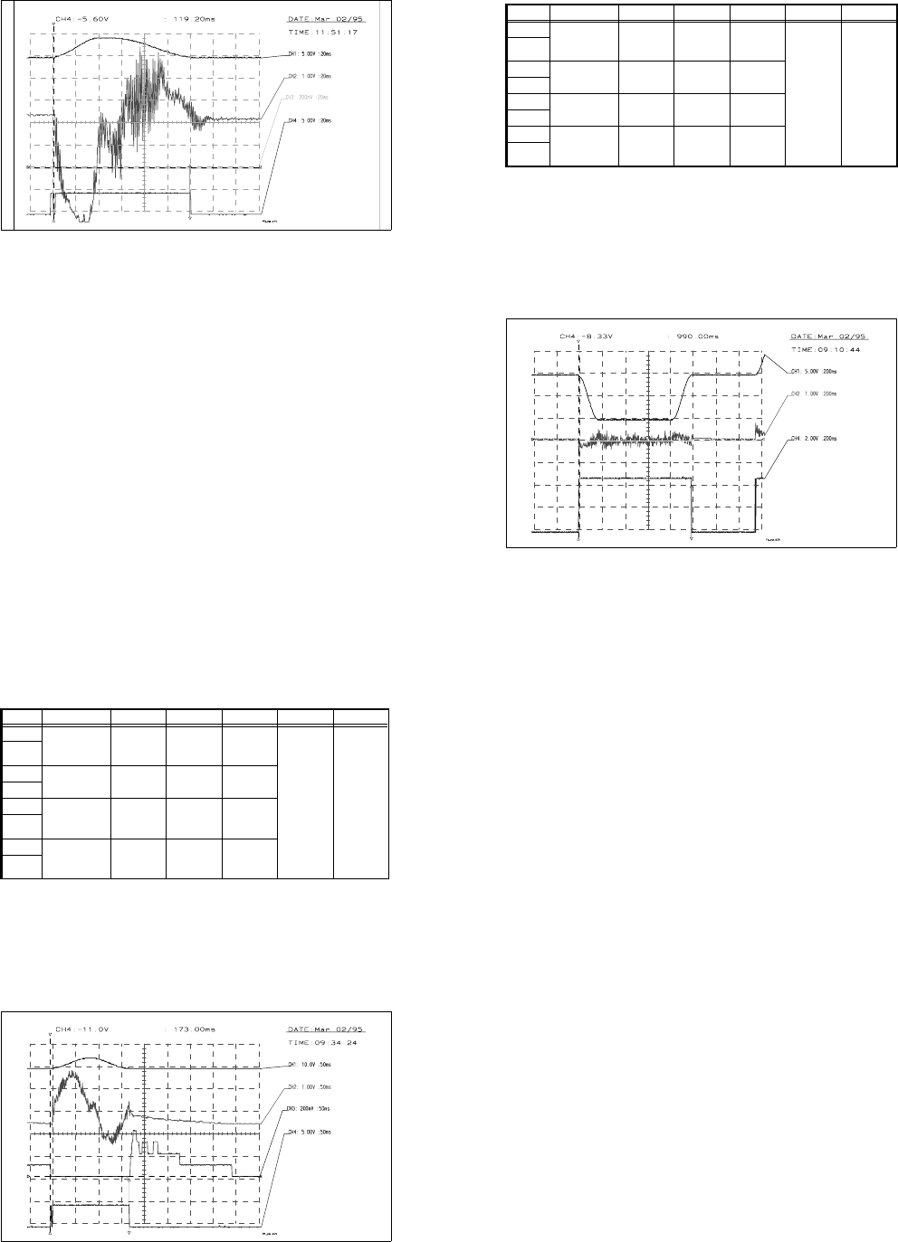
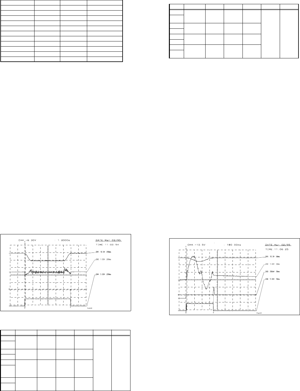
Setting the speed (see Fig. 10.3.15)
Preparation:
● Change the MA data for adjusting the speed and then reference the axis (see Table 10.3.2)
● Connect an axis test box to the axis board and set to time measurement - axis 0.
● Set the axis to continuous operation for a distance of 100,000 - 300,000 digits.
Setting:
● Increase the P gain on the servo board until the axis can be easily positioned.
● Use the tacho potentiometer on the X servo board to set the f/V converter signal at the diagn. strip
to the zero line ± 500 mV once the speed is reached (max. setpoint values) (see Fig. 10.3.15).
Check:
● The positioning time must be 980ms ±15ms (time measured with a suitable P gain)
Fig. 10.3.15 Setpoint value curve for adjusting the speed of the X axis
Input Test point Signal Coupling Y deflection Trigger X deflection
CH1 Axis test box,
setpoint value
BNC socket
Setpoint
value
DC 5.00 V/Div
CH4
10%
pre-trigger
200 ms
GND
CH2
Control unit
f/V converter
Signal from
f/V converter
DC 1.00 V/Div
GND
CH3
GND
CH4 Axis test box,
end signal
BNC socket
End signal DC 2.00 V/Div
GND
Tab. 10.3.7 Oscilloscope settings: Adjusting the speed of the X axis
Vnom. value
f/V converter signal
End signal
Adjust f/V converter signal to 0
If distance: 100000-300000
v: 10 accel.: 150 decel.: 150
time approx. 990ms +- 15ms
10 Siplace G automatic glue applicator SIPLACE 80S/80F/G Service Manual
Edition 06/98
10 - 54
Adjusting the P gain (see Fig. 10.3.16)
Preparation:
● Set the MA data as for adjusting the speed (see Table 10.3.2)
● Set the axis to continuous operation from 195,000 to 205,000.
Setting:
● Use the servo board potentiometer to increase the P gain until a slight tendency to vibrate occurs
at the position deviation.
● Reduce or increase the P gain until the position deviation no longer rises or dips (see Fig.
10.3.16).
Fig. 10.3.16 Setpoint value curve for adjusting the P gain for the X axis
Input Test point Signal Coupling Y deflection Trigger X deflection
CH1 Axis test box,
setpoint value
BNC socket
Setpoint
value
DC 5.00 V/Div
CH4
10%
pre-trigger
200 ms
GND
CH2
Test point 6,
servo board
Actual cur-
rent value
DC 1.00 V/Div
GND
CH3 Axis test box,
position devia-
tion BNC socket
Position
deviation
DC 200 mV/Div
GND
CH4 Axis test box,
end signal
BNC socket
End signal DC 2.00 V/Div
GND
Tab. 10.3.8 Oscilloscope settings: Adjusting the P gain for the X axis
Vnom value
MP6 current curve of servo board
Position deviation
End signal
P gain OK
If distance: 205000-195000
V: 10 accel.: 150 decel.: 150
SIPLACE 80S/80F/G Service Manual 10 Siplace G automatic glue applicator
Edition 06/98
10 - 55
Check:
● Set the positioning distance to 120,000-280,000 and 100,000-300,000.
● The position deviation and current curve must not rise for either distance.
● During the reference sequence, the axis must not rise or give off a loud humming noise.
● The positioning time for the distance 120,000 to 280,000 must be 815 ms ±10 ms.
● The positioning time for the distance 100,000 to 300,000 must be 980 ms
±
10 ms.
Positioning quality
Preparation:
● Reset the MA data to basic data (see Table 10.3.4) and reference the axis.
● Set the distance in accordance with the distance table (see Table 10.3.9) and check the position
deviation.
● 50ms after the end signal, the position deviation must not exceed 5 digits.
Check:
● Set the distance in accordance with the distance table and check the time. Check the settings and
the machine, if necessary.
● The end signal will not be output until the post-pulse oscillations in the position deviation have
fallen below the specified value (position deviation in REAL.MA), since this could cause signifi-
cant fluctuations in the positioning time.
10 Siplace G automatic glue applicator SIPLACE 80S/80F/G Service Manual
Edition 06/98
10 - 56
Checking the offset
See "Adjusting the offset".
Reset the MA data to basic data (see Table 10.3.4) and reference the axis.
10.3.6.6 Y axis, SIPLACE G
General preparatory work
● The gluing heads and cameras must be fitted in order to set the axes.
● Use an RC filter to record the current curve and the diagnostic strip test point signal.
● Carry out a head and Y axis reference sequence.
● Position the X axis at 200,000.
● Reference the Y axis
● Switch the machine on for approximately 30 minutes.
Setting the offset
Preparation:
● Connect an axis test box to the axis board and set the position display to axis number 1.
● Change the MA data for offset adjustment and reference the axis (see Table 10.3.1).
● Position the Y axis at 500,000.
Setting:
● Use the offset potentiometer on the servo board to set the axis position to 500,000
±
1 digit.
Check:
● The axis position display should not deviate from the value 500,000 by more than 1 digit.
Positions Setpoint time in ms Tolerance in ms Setting range in ms
199,900 - 200,100 55 10 45 - 65
199,800 - 200,200 75 15 60 - 90
199,600 - 200,400 80 10 70 - 90
199,000 - 201,000 105 15 90 - 120
198,000 - 202,000 125 15 110 - 140
197,000 - 203,000 145 15 130 - 160
195,000 - 205,000 175 15 160 - 190
190,000 - 210,000 250 15 235 - 265
175,000 - 225,000 385 15 370 - 400
150,000 - 250,000 595 15 580 - 610
100,000 - 300,000 1005 15 990 - 1020
Tab. 10.3.9 Distance table for the X axis, SIPLACE G
SIPLACE 80S/80F/G Service Manual 10 Siplace G automatic glue applicator
Edition 06/98
10 - 57
Setting the speed (see Fig. 10.3.17)
Preparation:
● Change the MA data for adjusting the speed (see Table 10.3.2) and reference the axis.
● Connect an axis test box to the axis board and set to time measurement - axis 1.
● Set the axis to continuous operation for a distance of 300,000 - 550,000 digits.
Setting:
● Increase the P gain on the servo board until the axis can be easily positioned.
● Use the tacho potentiometer on the Y-servo board to set the f/V converter signal to the zero line
±500mV (see Fig. 10.3.17) once the speed is reached (maximum setpoint values).
Check:
● The positioning time must be 1200ms ± 15ms (time measured with a suitable P gain).
Input Test point Signal Coupling Y deflection Trigger X deflection
CH1 Axis test box,
setpoint value
BNC socket
Setpoint
value
DC 5.00 V/Div
CH4
10%
pre-trigger
200 ms
GND
CH2
Control unit,
f/V converter
Signal from
f/V converter
DC 1.00 V/Div
GND
CH3
GND
CH4 Axis test box,
end signal
BNC socket
End signal DC 2.00 V/Div
GND
Tab. 10.3 - 10 Oscilloscope settings: Setting the speed of the Y axis
10 Siplace G automatic glue applicator SIPLACE 80S/80F/G Service Manual
Edition 06/98
10 - 58
Fig. 10.3.17 Setpoint value curve for adjusting the speed of the Y axis
Adjusting the P gain (see Fig. 10.3.18)
Preparation:
● Set the MA data as for adjusting the speed (see Table 10.3.2).
● Set the axis to continuous operation for a distance of 395,000-405,000 digits.
Setting:
● Use the potentiometer on the servo board to increase the P gain until a slight tendency to vibrate
can be seen in the position deviation (see Fig. 10.3.18).
Input Test point Signal Coupling Y deflection Trigger X deflection
CH1 Axis test box,
setpoint value
BNC socket
Setpoint
value
DC 5.00 V/Div
CH4
10%
pre-trigger
200 ms
GND
CH2
Test point 6,
servo board
Actual cur-
rent value
DC 1.00 V/Div
GND
CH3 Axis test box
position devia-
tion BNC
socket
Position
deviation
DC 200 mV/Div
GND
CH4 Axis test box,
end signal
BNC socket
End signal DC 2.00 V/Div
GND
Tab. 10.3 - 11 Oscilloscope settings: adjusting the P gain for the Y axis
Vnom value
f/V converter signal
End signal
Adjust f/V converter signal to 0
If distance: 550000-300000
v: 10 accel.: 200 decel.: 200
SIPLACE 80S/80F/G Service Manual 10 Siplace G automatic glue applicator
Edition 06/98
10 - 59
● Reduce or increase the P gain until the position deviation no longer rises or dips.
Fig. 10.3.18 Setpoint value curve for the P gain for the Y axis
Check:
● Set the positioning distance to 350,000 - 450,000 and 300,000 - 500,000.
● The position deviation and current curve must not rise at either distance.
● During the reference sequence, the axis must not rise or give off a loud humming noise.
● Set the axis to continuous operation for a distance of 350,000 - 450,000 digits: positioning time
approximately 580
±
10ms
● Set the axis to continuous operation for a distance of 300,000 - 500,000 digits: positioning time
approximately 990 ±10ms
Positioning quality
Preparation:
● Reset the MA data to basic data (see Table 10.3.4) and reference the axis.
● Set the distance in accordance with the distance table (see Table 10.3.12) and check the position
deviation.
● 50ms after the end signal, the position deviation must not exceed 5 digits.
Check:
● Set the distance in accordance with the table (see Table 10.3.12) and check the time. Check the
settings or the machine, if necessary.
● The end signal will not be output until the post-pulse oscillations in the position deviation have
fallen below the specified value (position deviation in REAL.MA), since this could cause signifi-
cant fluctuations in the positioning time.
Vnom value
MP6 current curve of servo board
Position deviation
End signal
P gain OK
If distance: 395000-405000
v:10
Acceleration.: 200
Deceleration.: 200