80S-15贴片机.pdf - 第474页
SIPLACE 80 S/ F/G Service M anual 11 Control Unit Edition 04/97 11 - 5 11.1.4 Replacing Station Computer M 34 Spare pa rts KSP-M 34-A162 computer , from it em no. 0 0302834 -07 ● Discon nect all plug-in conne ctions o n …
11 Control Unit SIPLACE 80 S/F/G Service Manual
Edition 04/97
11 - 4
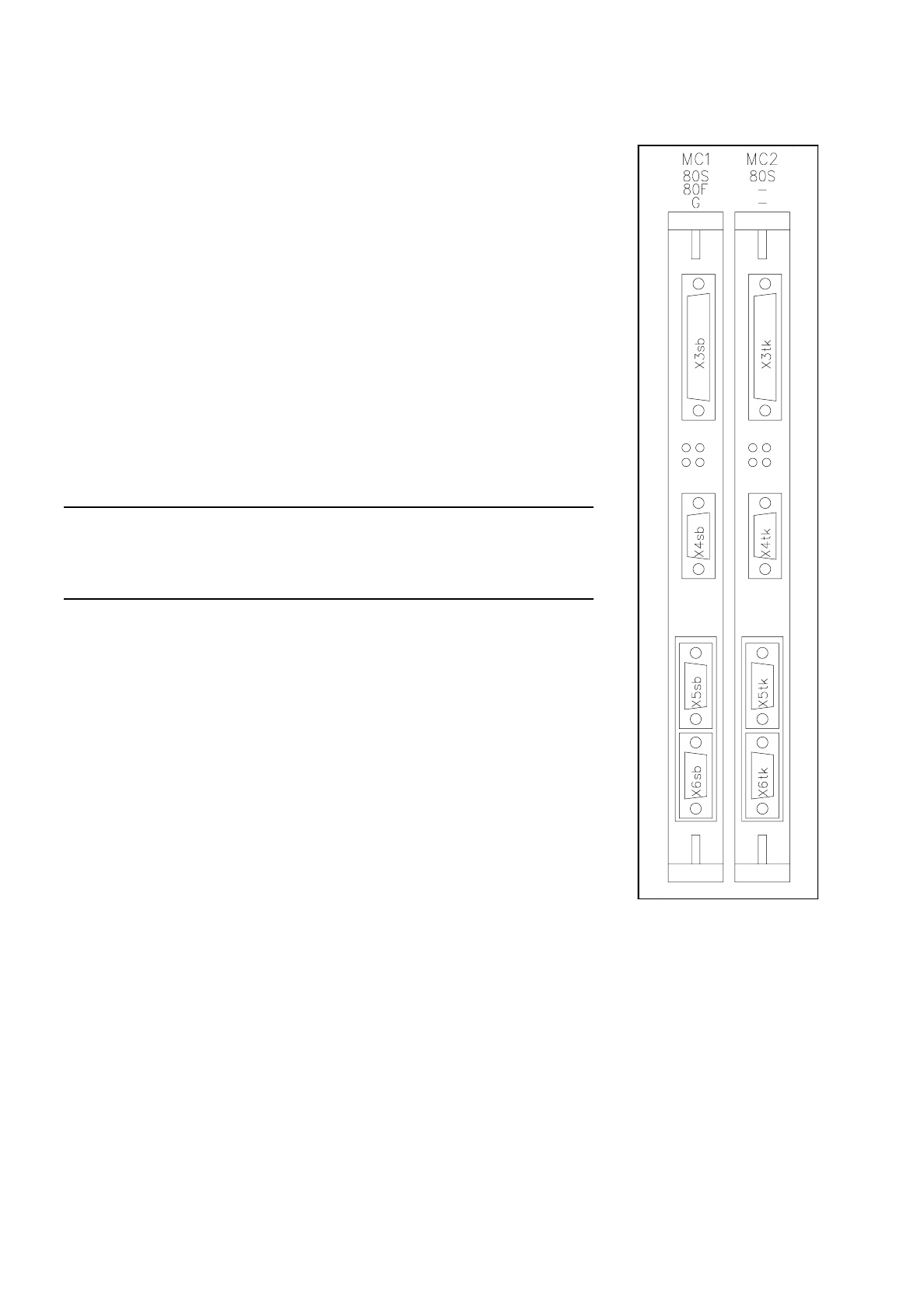
11.1.3 Replacing the Machine Controllers M18
Spare parts
Machine controller MC1, from item no. 00312349-10
Machine controller MC2, from item no. 00312351-10 (applies to 80S only)
●
Disconnect all plug-in connections on the front cover of the machine con-
troller (plug x3, x4, x5 and x6; see Fig. 11.1.1).
●
Undo the MC board’s front cover mounting screws (2 slotted-head
screws)
●
Carefully pull out the MC board.
●
Place the board on an ESD-checked surface.
●
Check the wrap wiring of the new machine controller against the list
MC1 see Section 11.4
MC2 see Section 11.5
●
To fit the boards proceed in the reverse sequence of operations.
NOTE
When inserting the connecting plugs make sure you have the correct slots on
the front panel.
Fig. 11.1.1 Machine controllers
MC1 and MC2
SIPLACE 80 S/F/G Service Manual 11 Control Unit
Edition 04/97
11 - 5
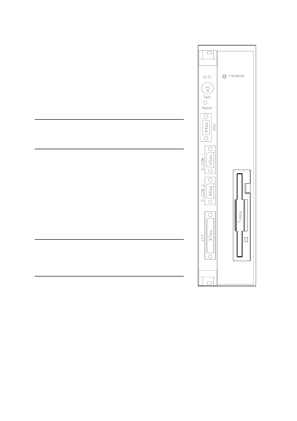
11.1.4 Replacing Station Computer M34
Spare parts
KSP-M34-A162 computer, from item no. 00302834-07
●
Disconnect all plug-in connections on the front cover of the sta-
tion computer (plugs x3, x4 sa, x5 sa; see Fig. 11.1.2).
●
Undo the station computer board’s front cover mounting screws
(2 slotted-head screws) and the hard disk / floppy disk board
mounting screws (4 slotted head screws).
NOTE
The station computer and the hard disk / floppy disk boards are
connected via two short ribbon cables.
●
Carefully pull out the station computer board and the hard disk /
floppy disk boards simultaneously.
●
Place the boards on an ESD-checked surface.
●
Check the wrap wiring of the new station computer against the
list (see Section 11.3).
●
Disconnect the connecting cable between the station computer
and the hard disk / floppy disk board.
●
Connect the new station computer board to the hard disk / floppy
disk board.
●
To fit the boards proceed in the reverse sequence of operations.
NOTE
When inserting the connecting plugs make sure you have the cor-
rect slots on the front panel.
Should you have lost the setup data for the M34 see Section 11.2.
Fig. 11.1.2 M34 computer -
hard disk/floppy disk

11 Control Unit SIPLACE 80 S/F/G Service Manual
Edition 04/97
11 - 6
11.1.5 Replacing the Hard Disk / Floppy Disk Board
Spare parts
Floppy/winchester AMS-M349-A100, from item no. 00319704-01
●
Disconnect all plug-in connections on the front panel of the station computer (plugs x3, x4 sa, x5 sa; see Fig.
11.1.2).
●
Unscrew and remove the MC board’s front cover mounting screws (2 slotted-head screws) and the hard disk /
floppy disk board mounting screws (4 slotted-head screws).
NOTE
The station computer and the hard disk / floppy disk boards are connected via two short flat ribbon cables.
●
Carefully pull out the station computer and hard disk / floppy disk boards. Place the boards on an ESD-
checked surface.
●
Disconnect the connecting cables between the boards (see the section
Replacing Computer M34
).
●
Insert the new hard disk / floppy disk board in the station computer board.
●
To fit the boards proceed in the reverse sequence of operations.
NOTE
When inserting the connecting plugs make sure you have the correct slots on the front panel. Should you have
lost the setup data for the M44 see Section 11.2.
●
Switch the machine on and install the current station software (see
Adjustment instructions
).
●
Copy the original MA data from the backup copy onto the hard disk.