80S-15贴片机.pdf - 第203页
SIPLACE 80 S/ F/G Service M anual 7 Components Table Edition 04/97 7 - 21 – None of the flap openers of a loc ation is bei ng activat ed: there is a fault in the 2.8 bar compr essed ai r branc h (see Sec tion a bove), or…

7 Components Table SIPLACE 80 S/F/G Service Manual
Edition 04/97
7 - 20
●
Remove the cover plate over the compressed air unit from the machine base (2 special socket-head cap
screws M3) and check the pressure for the flap opener on the lefthand pressure gauge of the compressed
air unit: it must show 2.8 bar.
–
If it does not, correct the pressure at the corresponding setting knob of the compressed air unit (for
setting, see User’s Manual, Section 9).
–
If the pressure was set correctly, proceed as follows:
DANGER
QQQ
Switch off the machine at the main switch and disconnect it from the power supply.
●
Open the protective cover.
●
Tighten up the threaded hose connections at the flap opener (see Fig. 7.4.1) and at the com-
pressed air unit. Make sure that the compressed air hose is not pinched or damaged.
●
If the compressed air hose has to be replaced,
switch off the machine at the main switch and
disconnect it from the power supply.
●
Switch off the compressed air at the shut-off valve of the compressed air unit (see User’s Manual,
Section 9) and replace the compressed air hose. Replace all cable lacings in their previous posi-
tion. Fit the cover plate back over the compressed air unit.
●
Please note: The compressed air hose at the flap opener connection must be routed between the
machine base and the clamping lever in order to keep it clear of the cutter wheel.
●
Make sure the plug connection X38 at the "Flap opener control" board is firmly seated and con-
tacting properly (position: on the left below the strip, see Fig. 7.4.2).
●
Continue work with the next section.
7.4.2.2 Checking Functioning and Continuing Fault Location
DANGER
OOO
The SITEST program must only be used by
authorized personnel who have been specially trained
in this
at Siemens AG (please observe the DANGER notes in section 7.6.2 on page 7 - 34).
●
Switch the machine on and load the SITEST program.
●
Select from within the SITEST main menu "Functions"
→
"BE table"
→
"Continuous loop CL"
→
"Magazine
opener". All of the flap openers of a location will activated one after the other.
●
Check whether the entire flap opener is not being activated or possibly only an individual plunger is not
extending or retracting. Finish continuous operation by selecting "finish":
●
If the flap openers of an entire location are not being activated, first check with "Continuous loop CL" acti-
vation in the opposite location.
●
If the flap openers of both locations (1 and 3) are not being activated, proceed as follows:
SIPLACE 80 S/F/G Service Manual 7 Components Table
Edition 04/97
7 - 21
–
None of the flap openers of a location is being activated: there is a fault in the 2.8 bar compressed air
branch (see Section above), or a defect in the "Flap opener control" board (see Fig. 7.4.2), or in the
cables between the flap openers interface and the communications unit.
●
Proceed as described in the next section
–
Individual flap openers are not being activated: To continue fault location, select:
"BE table"
→
"Single function"
→
"Adr. or track"
→
"Magazine openers":
●
Make sure which plunger is not extending or withdrawing at all or only incompletely.
The figures for the plunger stroke are shown in Fig. 7.4.3.
●
Replace the defective screw-in cylinder as described below.
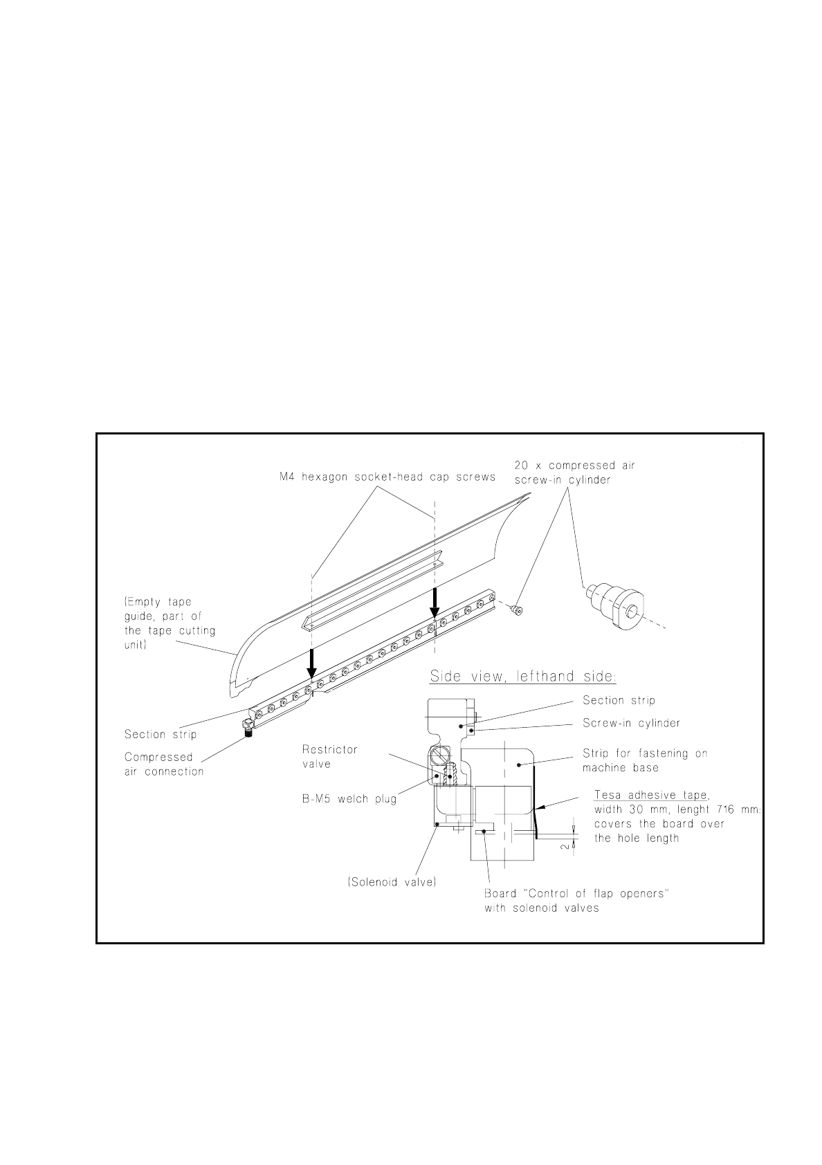
7.4.2.3 Replacing the Screw-In Cylinder, Replacing the Flap Opener Unit
Fig. 7.4.1 Replacing the screw-in compressed air cylinder, applying the Tesa adhesive tape

7 Components Table SIPLACE 80 S/F/G Service Manual
Edition 04/97
7 - 22
●
Complete the SITEST program and switch the machine off at the main switch.
●
Disconnect the machine from the main power supply!
●
Remove the cover over the compressed air unit (2 special socket-head cap screws M3) and in addition
switch off the compressed air at the shut-off valve of the compressed air unit (see User’s Manual, Section
9).
●
Open the protective cover over the corresponding flap opener.
●
Replacing the screw-in cylinder:
●
Unscrew and remove the leaky or stiff screw-in cylinder (use an open-ended spanner, size SW7).
●
Lubricate the o-ring of the new screw-in cylinder with vaseline before fitting it and screw in the screw-
in cylinder as far as the stop (see Fig. 7.4.1).
●
Close the protective covers, connect the machine to the power supply, switch on the compressed air
at the compressed air unit, switch the machine on, load the SITEST program and make sure that the
flap opener functions correctly, as described above.
●
Replacing flap openers
●
Pull off the adhesive tape on the longer side of the cast iron strip.
●
Undo the compressed air connection at the quick-release coupling of the flap opener (on the left, see
Fig. 7.4.1) and unplug the plug connection (X38) at the flap opener board (on the left beneath the strip,
see Fig. 7.4.2)
NOTE:
The "Flap opener control" board and the section strip with screw-in cylinders are only replaced together
(aligned unit = flap opener Siplace 80 Service).
Here the cast iron strip remains in position on the machine base. If it is removed you will need to align the
flap opener including cast iron strip to the components table when refitting it, as shown in Fig. 7.4.3, in
order to ensure the feeder modules are operating properly.
●
Undo the 2 socket-head cap screws M4 in the empty tape channel, remove the flap opener (see 1+2
in Fig. 7.4.2) from the cast iron strip, lifting the empty tape channel upwards and off.
●
Fit the new flap opener including empty tape channel to the cast iron strip (2 socket-head cap screws
M4).
●
Stick a new piece of Tesa adhesive tape to the longer side of the cast iron strip so that the board and
gap are covered over their entire width and length, as shown in Fig. 7.4.1.
●
Align the empty tape channel symmetrically with the pressure rod of the empty tape cutting device as
described in section 7.6 "Empty Tape Cutting Unit and Empty Tape Channel".
●
Close the protective covers, connect the machine to the power supply, switch on the compressed air
at the compressed air unit, switch on the machine at the main switch, check the 2.8 bar pressure.
●
Load the SITEST program and make sure the flap opener functions correctly, as described above.
●
Fit the cover over the compressed air unit, load the station software.