80S-15贴片机.pdf - 第235页
SIPLACE 80 S/ F/G Service M anual 7 Components Table Edition 04/97 7 - 53 7.6.13 Empty Tape Channel: Checking and Replacing the Spring Bows If indiv idual tape s are no t being cut (tap e jam in i ndividual feeder mo dul…
7 Components Table SIPLACE 80 S/F/G Service Manual
Edition 04/97
7 - 52
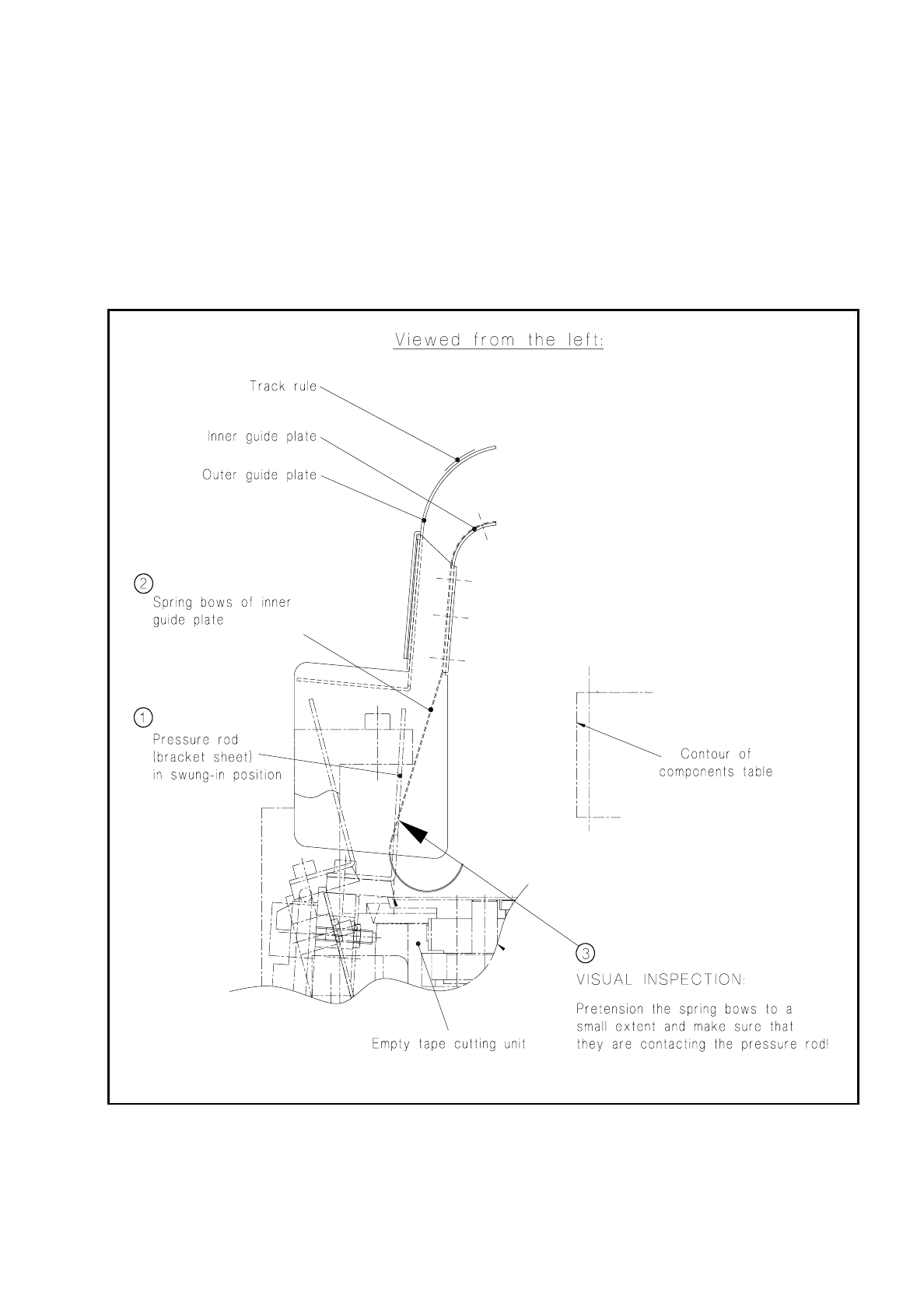
Fig. 7.6.7 Checking the spring bows in the empty tape channel (guide plate, inner)
SIPLACE 80 S/F/G Service Manual 7 Components Table
Edition 04/97
7 - 53
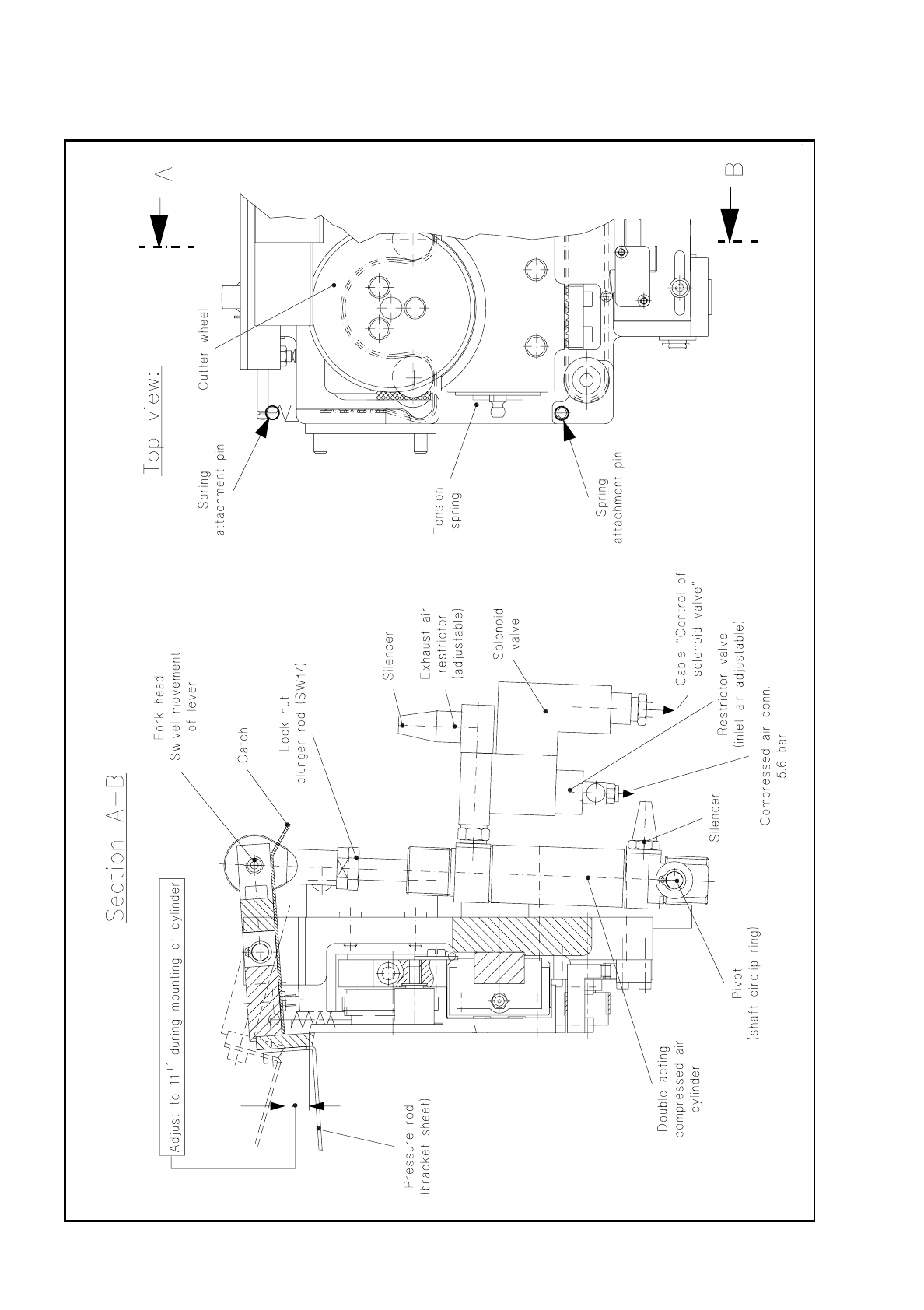
7.6.13 Empty Tape Channel: Checking and Replacing the Spring Bows
If individual tapes are not being cut (tape jam in individual feeder modules), this may be due to the "guide
plate, inner" having bent spring bows.
●
To check the spring bows proceed as shown in Fig. 7.6.8.
●
If individual spring bows are bent, install a new "empty tape channel complete".
●
Adjust the new empty tape channel so that it is positioned symmetrically to the pressure rod (see below).
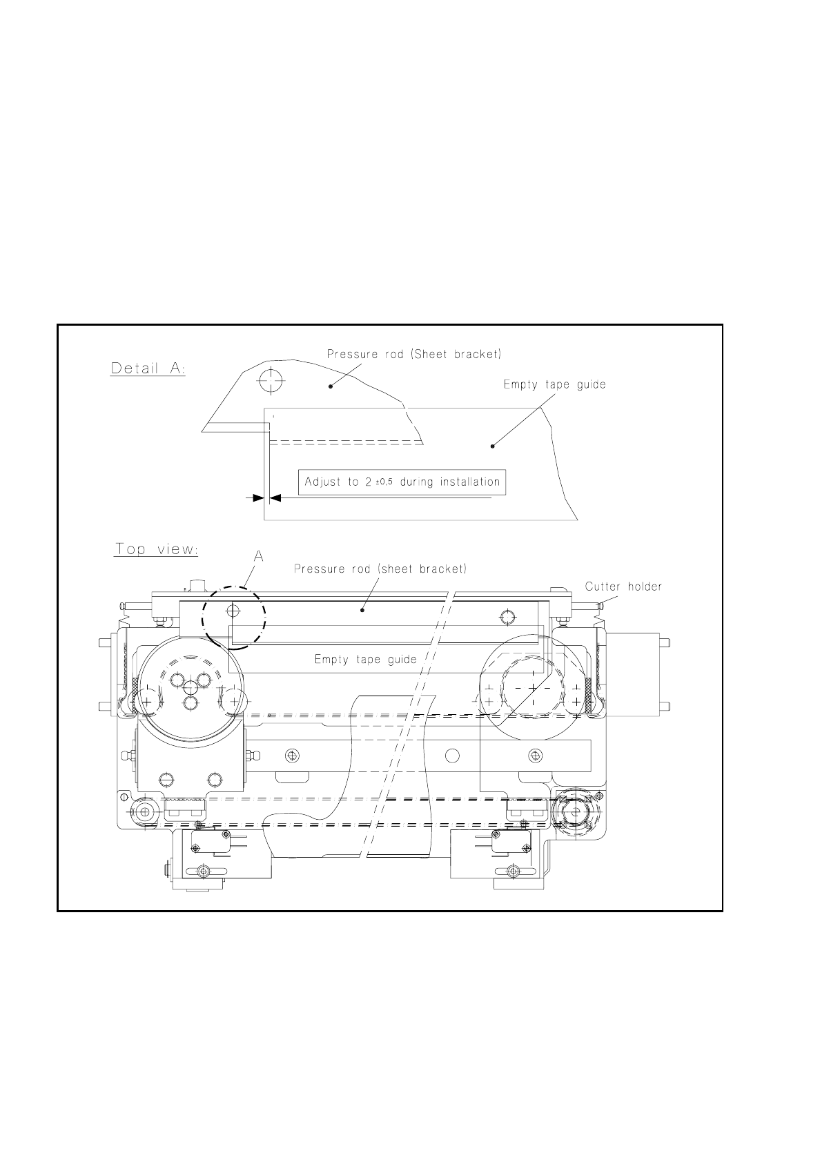
Fig. 7.6.8 Aligning the empty tape channel to the pressure rod when refitting
7 Components Table SIPLACE 80 S/F/G Service Manual
Edition 04/97
7 - 54
7.6.14 Fitting and Aligning the Empty Tape Cutting Unit and Empty
Tape Channel
With this work it is assumed that the flap opener including strip has already been correctly aligned after rein-
stallation (see section 7.4 "Flap Opener (Magazine Openers)").
In the following cases align the empty tape channel symmetrically to the pressure rod:
–
In the event of a fault, as when the outer tapes in each case (tracks 1/120) are not being cut correctly.
–
When refitting the empty tape cutting unit, the flap opener and/or the empty tape channel.
Fig. 7.6.9 Aligning the empty tape channel to the pressure rod when refitting
●
Reinstalling and adjusting the empty tape channel:
If it is only the empty tape channel which has been replaced, proceed as follows.
●
If necessary, unscrew the mounting of the empty tape channel to the flap opener (2 socket-head cap
screws M4, see Fig. 7.1.3 in section 7.1 "Overview") and align the empty tape channel symmetrically
to the pressure rod of the cutting unit as shown in Fig. 7.6.9.
●
Screw down the guide channel in this position on the flap opener (2 socket-head cap screws M4).