80S-15贴片机.pdf - 第322页
9 Revolver Head SIPLACE 80S/F/G Service Manual Edition 04/97 9 - 38 The moto r control board 1710460- Y0009 con trols th e screwdr iver un it 1. Fig . 9.5.11 sh ows the princi ple behind the deter mination of the rota ti…
SIPLACE 80S/F/G Service Manual 9 Revolver Head
Edition 04/97
9 - 37
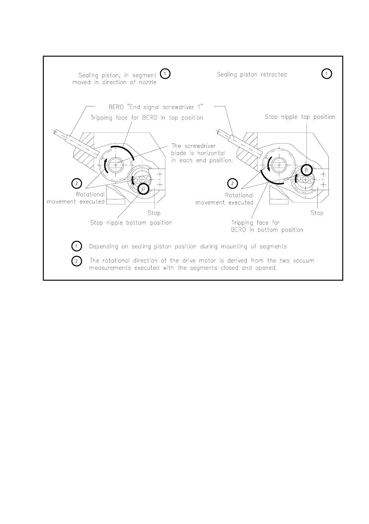
Fig. 9.5.11 Determination of the direction of rotation of the screwdriver unit 1
On the motor shaft sits the gearwheel with stop nipple which limits rotational movement at the stop to 180° in
each case. The stop is screwed to the segment claw.
The sealing piston is held in the respective end position by means of holding current. The screwdriver itself is
a gearwheel with a turned-on shaft. The shaft at one end is mounted in a miniature ball bearing, at the other in
a deep-grooved ball bearing. The motor pinion meshes with the teeth of the gearwheel.
The shaft end pointing to the segment claw is flattened on two opposite sides and forms the screwdriver unit
blade. Accordingly, the screwdriver engages with the slot in the eccentric shaft of the segment in the revolver
head station 1. For an area extending over 90° the gearwheel has no teeth (see Fig. 9.5.10). When the
screwdriver rotates, this section activates the bero in the segment claw. It sends the end signal when the
screwdriver has completed its rotation.
The bero cable runs in the recess in the lifting slide to the screwdriver 1 conversion board and from there is
routed to the plug at the "Small axis" conversion board 1710460-Y0005. A cable bracket above the segment
claw protects it against being damaged when the sz axis moves.

9 Revolver Head SIPLACE 80S/F/G Service Manual
Edition 04/97
9 - 38
The motor control board 1710460-Y0009 controls the screwdriver unit 1. Fig. 9.5.11 shows the principle
behind the determination of the rotational movement for opening and closing the segment.
NOTE
The screwdriver unit blade must always be horizontal or the eccentric shaft of the segment will jam at the
screwdriver. The revolver head cannot be cycled on (see also the section 9.8 ”Segments”).
9.5.7 Screwdriver Unit 2 (Ejection and Checking the Nozzle)
Screwdriver unit "2" (see Fig. 9.5.12) moves the sealing piston of the segment in revolver head station 3. It is
mounted on the lifting slide housing (see 9.5.5.1) in revolver head station 3.
In revolver head station 3 components will be ejected and the segment closed under the following fault
conditions:
–
Components not correctly picked-up
–
Components with vacuum error "Good or bad nozzle contact"
–
Components with CRDL measurement error, rotational or centering error
In addition, during the placement cycle the nozzle will be checked for contamination as described in the sec-
tion 9.5.4 ”Vacuum Measuring Board”. The sealing piston is retracted by the screwdriver rotating by 180° and
thus at the same time the vacuum duct of the segment is opened. This is followed by the screwdriver rotating
by a further 180° but in the opposite direction which causes the sealing piston to move forward, thus closing
the segment again. The closed segment is cycled on with the revolver head.
The movement of screwdriver 2, like that of screwdriver 1, is signalled by the bero as an end signal to the
input board of the control unit. Screwdriver unit 2 is controlled, like screwdriver unit 1, by the motor controller
board 1710460-Y0009.
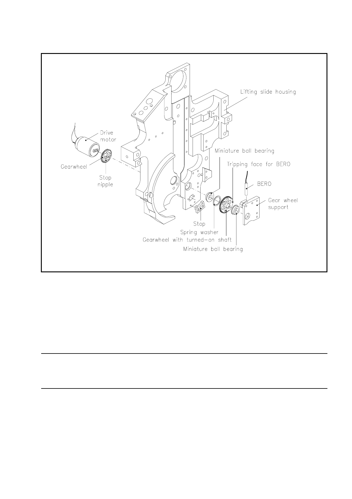
Screwdriver unit 2 in revolver head station 3 (see Fig. 9.5.12) consists of the following components:
–
drive motor
–
gearwheel with stop nipple
–
stop for limiting the rotational movement
–
gearwheel support
–
gearwheel with tripping face for the bero and screwdriver unit blade
–
miniature ball bearing (2 of these)
–
spring lock washer
SIPLACE 80S/F/G Service Manual 9 Revolver Head
Edition 04/97
9 - 39
Fig. 9.5.12 Screwdriver unit 2
The drive motor sits in the hole in the position of revolver head station 3.
The gearwheel on the motor shaft meshes with the teeth of the gearwheel with turned-on shaft which is
mounted at each end in 2 miniature ball bearings. The miniature ball bearing at the revolver head end is
accommodated in the gearwheel support. The screwdriver unit blade engages with the slot in the segment at
revolver head station 3. The screwdriver unit blade must be at an angle of 30° to the sz axis (see Fig. 9.5.13).
NOTE
If the screwdriver unit blade does not make an angle of 30° with the sz axis, the screwdriver unit blade will not
be able to slide in die groove of the cam. The revolver head will jam.
The bero is inserted from above into the hole in the gearwheel support and fixed at the corresponding trigger-
ing distance. The toothless section of the gearwheel circumference is used for as a sensing face for the bero
and triggers the end message for rotation of the screwdriver.