80S-15贴片机.pdf - 第462页
10 Si plac e G au tom atic g lue ap plic ator SIPLA CE 80 S/80 F/G Servi ce Ma nua l Ed itio n 06 /98 10 - 44 10.3.6.2 Axis settings Settin gs for adjust ing the offset Settin gs for adjust ing the speed (potent iometer …
10 Siplace G automatic glue applicator SIPLACE 80S/80F/G Service Manual
Edition 06/98
10 - 40
● Move the gluing head holder to the minimum position.
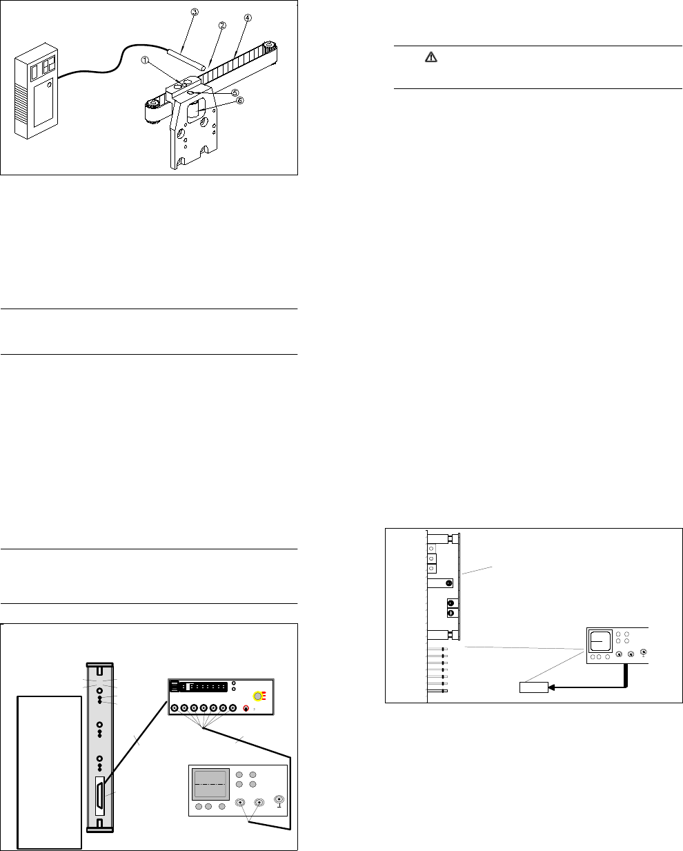
Fig. 10.3.5 Overview: Tensioning the toothed belt on the X2 axis (illustrated without glue application head)
Key to
1 Free hole for moving the idler pulley
2 Test point (half-way along the free belt length)
3 Measuring head (illustrated without the stand)
4 Free end of the belt
5 Fixing screw for the idler pulley
6 Idler pulley
● Attach the belt tension measuring device. Position the measuring head just beside the free end of the belt
(approximately 5 - 20 mm). The test point is around half-way along the free belt length (see Fig. 10.3.5).
● Switch on the belt tension measuring device. If "LO BAT" appears on the display, the battery will have to be
charged first.
● Strike the belt sharply to start it vibrating.
PLEASE NOTE
The belt must not be twisted when you strike it since this would make it wobble as it vibrates. Consequently,
as far as possible, you should strike the belt over the entire width. Use an appropriate tool to strike the belt,
e.g. an Allen key. Do NOT strike the belt with your finger.
● The measurement is indicated on the belt tension measuring device in the form of an audible signal. The
measured frequency appears on the display.
● Tensioning the toothed belt:
● Loosen the fixing screw on the idler pulley (see Fig. 10.3.5).
SIPLACE 80S/80F/G Service Manual 10 Siplace G automatic glue applicator
Edition 06/98
10 - 41
● Push a suitable pin (e.g. drift punch or screwdriver) into the free hole in the toothed belt fastener.
● Use the pin to press the idler pulley against the toothed belt (see Fig. 10.3.5). You could also use the
fixing screw to push the idler pulley. At the same time, tighten the fixing screw of the idler pulley once
more.
● Change the belt tension until the required frequency is reached:
182 Hz (for both toothed belts).
CAUTION
The toothed belt can become stretched if it is overtightened. Precise positioning is not possible if the
toothed belt is stretched.
● Remove the belt tension measuring device.
● Mount the glue application head.
● Close the protective cover and release the emergency stop button.
10 Siplace G automatic glue applicator SIPLACE 80S/80F/G Service Manual
Edition 06/98
10 - 42
10.3.6 Adjusting the dynamic behavior of the axes
PLEASE NOTE
- It is only necessary to fundamentally change the dynamic behavior of the axes after certain servicing work,
so check the dynamic behavior before you make any changes.
- Switch the machine on for at least half an hour before you make any adjustments.
- Always adjust the axis boards before adjusting the dynamic behavior of the axes (see Section 10.3.6.1).
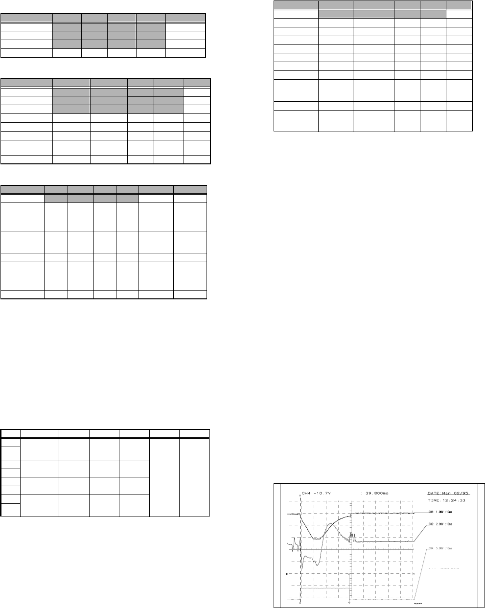
Fig. 10.3.6 Test set-up for axis boards
o
o
Endemeldung
Aus / Ein
Initialisiert
O - Impuls
Soll - Poti
Kraft - Poti
Schnittstelle für die
Meßbox
o
o
oo
oo
o
o
oo
oo
o
o
oo
oo
1. Achse 1 Analogmasse
2. Achse 1 Geschwindigkeit
4. Ac hse 1 Endemeldung
3. Achse 1 Kraft
5. Achse 1 Spur A
6. Achse 1 Spur B
7. Achse 1 Nullimpuls
8. Achse 2 Anzeigesignal
9. Achse 2 Geschwindigkeit
11. Achse 2 Endemeldung
10. Achse 2 Kraft
12. Achse 2 Spur A
13. Achse 2 Spur B
14. Achse 2 Nullimpuls
15. Achse 3 Anzeigesignal
16. Achse 3 Geschwindigkeit
18. Achse 3 Endemeldung
17. Achse 3 Kraft
19. Achse 3 Spur A
20. Achse 3 Spur B
21. Achse 3 Nullimpuls
22. GND
23. + 5V-
24. +15V-
25. - 15V-
Steckerbelegung
( Meßbox )
Achse 1
Achse 2
Achs e 3
Reset
AUS
EIN
Nullimpuls
Endemeldu ng
Spur A Spu r B Nullimpuls Sollwert Kraft
Ende
Meldung
Positions
Abweich ung
Synchronisierung
0,1 V^
=
1 Digit
SIEMENS AG
AUT51 - QS
CH1 CH2
XY
Verbindungskabel
BNC-Kabel
Zero pulse
End signal
Connection cable
Test box interface
BNC cable
1. Axis 1 Analog ground
2. Axis 1 Speed
3. Axis 1 Power
4. Axis 1 End signal
5. Axis 1 Track A
6. Axis 1 Track B
7. Axis 1 Zero pulse
8. Axis 2 Display signal
9. Axis 2 Speed
10. Axis 2 Force
11. Axis 2 End signal
12. Axis 2 Track A
13. Axis 2 Track B
14.Axis 2 Zero pulse
15. Axis 3 Display signal
16. Axis 3 Speed
17. Axis 3 Force
18. Axis 3 End signal
19. Axis 3 Track A
20. Axis 3 Track B
21.Axis 3 Zero pulse
22.GND
23.+ 5 V-
24.+ 15 V-
25.- 15 V-
Plug assignment
test box
Initialized
Off/On
Vnom potentiom.
Force potentiom.
SIPLACE 80S/80F/G Service Manual 10 Siplace G automatic glue applicator
Edition 06/98
10 - 43
Fig. 10.3.7 Test set-up for servo boards
10.3.6.1 Adjusting the axis boards
Use the SIPLACE axis testing device to set the axis boards.
● Connect the input of the axis testing device to the axis board to be set (see Fig. 10.3.6).
● Connect a digital multimeter to the "v
nominal
" socket on the back of the axis testing device.
● Set the axis selector switch to the axis to be tested.
● Use the "Setpoint" potentiometer on the front of the axis board (see Fig. 10.3.6) to set
0V ±2mV.
● Connect a digital multimeter to the "Force" socket on the back of the axis testing device.
● Use the "Force" potentiometer on the front of the axis board (see Fig. 10.3.6) to set
0V ±2mV.
● Repeat the procedure for all the axes (3 per axis board).
Offset Drehzahlregler
Impulsstrom Isp. über Festwiderstand
Verstärkung P Ant.
Tacho V
Effektivstrom I eff über Festwiderstand
grün = Betriebsbereit
rot = Störung / Tachobruch bei X- und Y - Achse
MP1 Drehzahlsollwert
MP2 Stromsollwert
MP3 Ausgang Stromregler
MP4 Stromgrenzwert extern
MP5 Tachospannung
MP6 Stromistwert
Flügelplatine
gel b
grün
rot
0 V
gelb = I t - Meldung
2
CH1 CH2
X
Y
Oszillograph
green
yellow
red
yellow = I²t message
green = standby
red = fault / tacho break on X and Y axis
Wing-type board
Speed regulator offset
P gain
Tacho gai n
Power pulse current lsp over fixed resistance
I
r.m.s
current over fixed resistance
Oscillograph
0V
MP1 Speed offset
MP2 Current setpoint value
MP3 Current regulator output
MP4 External current threshold
MP5 Tacho voltage
MP6 Actual current value
RC-Filter
10 Siplace G automatic glue applicator SIPLACE 80S/80F/G Service Manual
Edition 06/98
10 - 44
10.3.6.2 Axis settings
Settings for adjusting the offset
Settings for adjusting the speed (potentiometer tacho)
Settings for adjusting the positioning quality (P gain)
Axis X1 Y1 X2 Y2 Z 1-3
Mode 1
4 4
4 4 4
Position deviation
100 100
100 100 10
KI
0 0
0 0 0
Position
200,000 500,000
0 0 0
Tab. 10.3.1 Settings for adjusting the offset
Axis X1 Y1 X2 Y2 Z 1-3
Mode 1 4 4 4 4 4
Position deviation
5 5
2 210
KI 1 1 1 10
Speed
10 10
10 10 4
Acceleration 150 200 100 100 100
Deceleration
150 200
50 50 50
Positioning distance
Waiting time 900ms
100,000 - 300,000 300,000 - 550,000 0 - 2,800 0 - 2,800 0 - 400
Achievable time
980 ± 15 1200 ± 15
119 ± 5 119 ± 5 39 ± 2
Tab. 10.3.2 Settings for adjusting the speed (potentiometer tacho)
Axis X1 Y1 X2 Y2 Z 1-3 Z 1-3
Mode 1 4 4 4 4 4 4
Setting distance
195,000
-
205,000
395,000
-
405,000
0
-
2,800
0
-
2,800
New calibra-
tion tool com-
partment;
current sensor
Old calibra-
tion tool com-
partment;
current sensor
Speed, control dis-
tance 1
Waiting time 900ms
120,000
-
280,000
350,000
-
450,000
-- - -
Time (ms)
815 ± 10 580 ± 10 -- - -
Speed, control dis-
tance 2
Waiting time 900ms
100,000
-
300,000
300,000
-
500,000
0
-
2,800
0
-
2,800
New calibra-
tion tool com-
partment;
current sensor
Old calibra-
tion tool com-
partment;
current sensor
Time (ms)
980 ± 10 990 ± 10
119 ± 5 119 ± 5 52 ± 2 47 ± 2
Tab. 10.3.3 Settings for adjusting the positioning quality (P gain)
SIPLACE 80S/80F/G Service Manual 10 Siplace G automatic glue applicator
Edition 06/98
10 - 45
Settings for checking the positioning quality/basic data
Axis X1 Y1 X2 Y2 Z 1-3
Mode 1 60 60 60 60 4
Mode 3
34
5 5 0
Positional deviation 55 2 2 10
Speed
10 10
10 10 4
Acceleration 150 200 100 100 100
Deceleration
150 200
50 50 50
KP 33 10 10 10
KI
11
1 1 0
Distance
Waiting time 900ms
Distance table Distance table
0
-
2,800
0
-
2,800
Time (ms)
Table Table
130 ±10 130 ± 10
Minimum quality
Deviation after end
signal
5 dgt 50 ms 5 dgt 50 ms
2 dgt
50 ms
2 dgt
50 ms
Tab. 10.3.4 Settings for checking the positioning quality/basic data
10 Siplace G automatic glue applicator SIPLACE 80S/80F/G Service Manual
Edition 06/98
10 - 46
10.3.6.3 Adjusting the dynamic behavior of the z axes
Preparation
● Set up glue application heads 1, 2 and 3 with a full glue cartridge.
● Carry out the zero point correction for the z axis(es), if necessary. Ensure that the zero point correction for
the z axis(es) was entered correctly in the MA data.
● Carry out a head reference run.
● Use an RC filter for the current curve (see Fig. 10.3.7).
Adjusting the offset
● Connect the axis testing device to the Z axis board. Use the momentary-contact switch on the axis testing
device to select position display 4 to 6 corresponding to the z axis concerned.
● Set the axis position to 0 ± 1 digits using the offset potentiometer on the servo board.
● Check: The position display must not fluctuate from the value by more than 1 digits.
Setting the speed
● Set the axis testing device to time measurement (set the toggle switch to -1), rotary switch, axis 0 to 2.
● Ensure that the space beneath the z axis is clear.
● Start the axis in continuous mode. Distance: 0 to 400 digits.
● Increase the P gain on the servo board until the axis can be easily positioned.
● Use the tacho potentiometer on the servo board to set the end message signal to 39 ms ± 2 ms (Z dis-
tance down, see Fig. 10.3.8).
● Check: the positioning time for z axis down must be 39 ms ± 2 ms and z axis up must be 40 ms ± 2 ms.
Adjusting the positioning quality
● Push the glue application head to be set over the calibration tool compartment.
● Start the axis in continuous mode. Distance: 0 to pos. calibration tool compartment for the "current sensor"
positioning type.
● Use the ratio potentiometer on the servo board to increase/reduce the P gain until the rising edge of the
setpoint value (at the transition to the position control) clearly starts to round off (see Fig. 10.3.9).
● The current curve must not rise sharply as shown in Fig. 10.3.11.
Input Test point Signal Coupling Y deflection Trigger X deflection
CH1 Axis test box,
setpoint value
BNC socket
Setpoint
value
DC 1.00 V/Div
CH 1
neg. edge
10%
pre-trigger
10 ms
GND
CH2
Test point 6,
servo board
Actual cur-
rent value
DC 2.00 V/Div
GND
CH3
GND
CH4 Axis test box,
end signal BNC
socket
End signal DC 5.00 V/Div
GND
Tab. 10.3.5 Z axis adjustment: connecting and setting an oscilloscope
SIPLACE 80S/80F/G Service Manual 10 Siplace G automatic glue applicator
Edition 06/98
10 - 47
● Readjust the speed using the tacho potentiometer on the servo board:
- If you are using the old metal calibration tool compartment, the positioning time for z axis down must
be 47 ms ± 2 ms.
- If you are using the new plastic calibration tool compartment, the positioning time for z axis down must
be 52 ms ± 2 ms.
● Check: If the P gain is set incorrectly, the setpoint value will not round off or the current curve will rise
sharply (see Fig. 10.3.10 or Fig. 10.3.11).
- Old calibration tool compartment: positioning time for axis down = approximately 47 ms ± 2 ms, axis
up = 49 ms ± 2 ms.
- New calibration tool compartment: positioning time the axis down = approximately 52 ms ± 2 ms, axis
up = 54 ms ± 2 ms.
Checking the offset
See "Adjusting the offset".
Reset the MA data to basic data (see table 10.3.4) and reference the axis.
Fig. 10.3.8 Diagram: Speed and P gain for z axes
MP6 current curve of servo board
End signal
If distance: 000000-000400
V: 10
acceleration: 100
deceleration: 50
Time approx. 39ms +- 2ms
Vnom value
10 Siplace G automatic glue applicator SIPLACE 80S/80F/G Service Manual
Edition 06/98
10 - 48
Fig. 10.3.9 Diagram: Speed and P gain for z axes
Fig. 10.3.10 Diagram: P gain too low for z axes
Old calibration tool
compartment
End signal
If distance: 000000-calibration
part compartment
v: 10
acceleration: 100
deceleration: 50
time approx. 47 ms +- 2ms
Vnom value
P gain o.k.
MP6 current curve of servo board
Old calibration tool
compartment
MP6 current curve of servo
board
End signal
If distance: 000000-calibrating
path compartment
V: 10
acceleration: 100
deceleration: 50
Vnom value
P gain too low
SIPLACE 80S/80F/G Service Manual 10 Siplace G automatic glue applicator
Edition 06/98
10 - 49
Fig. 10.3.11 Diagram: P gain too high for z axes
10.3.6.4 Adjusting the dynamic behavior of the X2/Y2 axis
Preparation
● Set up glue application heads 1 and 2 with a full glue cartridge.
● Carry out a head reference run.
● Use an RC filter for the current curve (see Fig. 10.3.7).
Input Test point Signal Coupling Y deflection Trigger X deflection
CH1 Axis test box,
setpoint value
BNC socket
Setpoint
value
DC 5.00 V/Div
CH4
10% pre-
trigger
20 ms
GND
CH2
Test point 6,
servo board
Actual cur-
rent value
DC 1.00 V/Div
GND
CH3 Axis test box,
position
deviation
BNC socket
Position
deviation
DC 200 mV/Div
GND
CH4 Axis test box,
end signal
BNC socket
End signal DC 5.00 V/Div
GND
Tab. 10.3.6 Parameters for setting the oscilloscope: Adjusting the dynamic behavior of the X2/Y2 axis
Old pos. calibration tool
compartment
MP6 current curve of servo board
End signal
P gain too high
If distance: 000000- pos. cali-
bration tool compartment
v: 10
acceleration: 100
deceleration: 50
time approx 47ms +- 2 ms
Vnom value
10 Siplace G automatic glue applicator SIPLACE 80S/80F/G Service Manual
Edition 06/98
10 - 50
Adjusting the offset
● Connect the axis testing device to the axis board. Select the axis on the axis testing device (2 or 3).
● Change the MA data for adjusting the offset using the values in the table 10.3.1.
Then reference the axis.
● Use the offset potentiometer on the servo board to set the axis position to 0 ± 1 digits.
● Check: the position display must not deviate from the value 0 by more than 1 digit.
Setting the speed
● Change the MA data for setting the tacho using the values in the table 10.3.2.
Then reference the axis.
● Set the axis testing device to time measurement (set the toggle switch to -1) and set the rotary switch for
axis 0 to 1.
● Start the axis in continuous mode. Distance: 0 to 2,800 digits.
● Increase the P gain on the servo board until the axis can be easily positioned.
● Use the tacho potentiometer on the servo board to set the end message signal to 119 ms ± 5 ms.
● Check: the positioning time must be 119 ms ± 5 ms (measured with a suitable P gain).
Adjusting the P gain
● Set the MA data as for setting the tacho.
● Start the axis in continuous mode. Distance: 0 to 2,800 digits.
● Use the ratio potentiometer on the servo board to increase the P gain until a slight tendency to vibrate can
be seen on the current curve.
● Increase/reduce the P gain until the position deviation no longer dips or rises (see Fig. 10.3.13 to Fig.
10.3.14).
● Use the tacho potentiometer on the servo board to adjust the speed to 119 ms ± 5 ms.
● Check: Start the axis in continuous mode. Distance: 0 to 2,800 digits.
- The P gain must be set so that the position deviation no longer dips or rises.
- For a distance of 0 to 2,800 digits, the positioning time must be 119 ms ± 5 ms.
Checking the positioning quality in accordance with table 10.3.4
● Reset the MA data to the basic data and reference the axis.
● Start the axis in continuous mode. Distance: 0 to 2,800 digits.
● 50 ms after the end signal, the position deviation must not exceed 2 digits.
Checking the offset
See "Adjusting the offset".
Reset the MA data to basic data (see Table 10.3.4) and reference the axis (all axes).
SIPLACE 80S/80F/G Service Manual 10 Siplace G automatic glue applicator
Edition 06/98
10 - 51
Fig. 10.3.12 Speed and P gain for the X2 axis (P gain OK)
Fig. 10.3.13 Speed and P gain for the X2 axis (P gain too low)
Vnom value
MP6 current curve of servo board
Positional deviation
End signal
P gain OK
If distance: 000000-002800
v: 10 accel.: 100 decel.: 50
Vnom value
MP6 current curve of servo board
Positional deviation
End signal
P gain too low
If distance: 000000-002800
v: 10 accel.: 100 decel.: 50