80S-15贴片机.pdf - 第293页
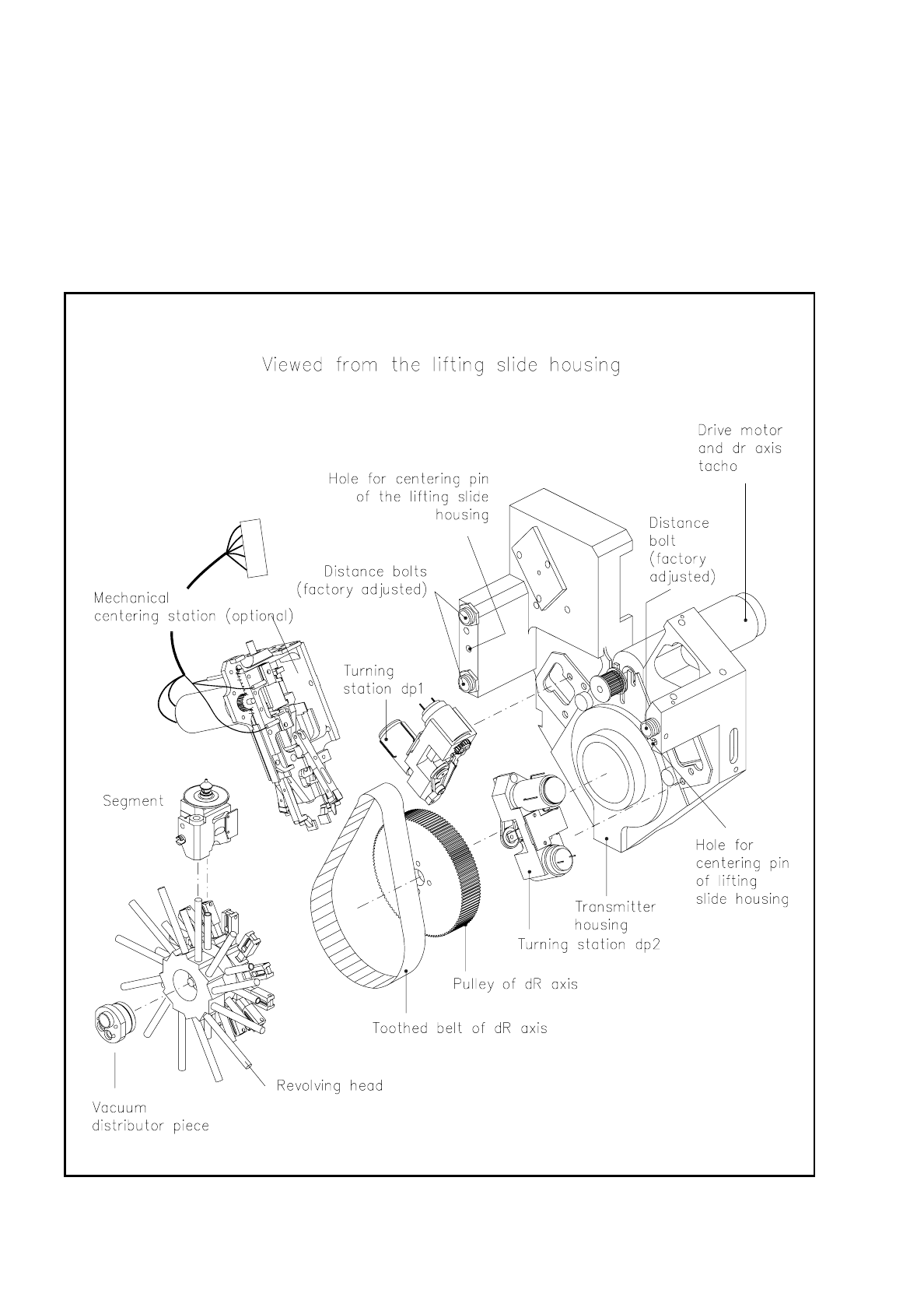
SIPLACE 80S/F/G Service Manual 9 Revolver Head Edition 04/97 9 - 9 Fig. 9.2.3 A ssemblies of the revolver head, part 3
9 Revolver Head SIPLACE 80S/F/G Service Manual
Edition 04/97
9 - 8
The revolver head consists of the following main assemblies (see Fig. 9.2.1 to Fig. 9.2.3):
–
Lifting slide housing (Fig. 9.2.1)
–
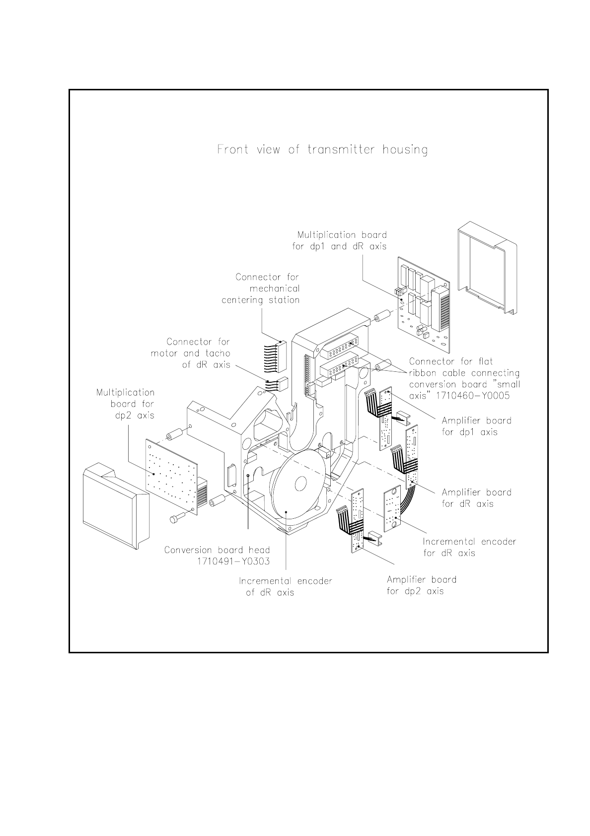
Encoder housing with revolver head (see Fig. 9.2.1 to Fig. 9.2.3) and optical components and board cen-
tering camera, lens and lighting
–
Segments (Fig. 9.2.2)
–
As an option, a mechanical centering station and CRDL testing station can be fitted as an upgrade.
Fig. 9.2.2 Assemblies of the revolver head, part 2
SIPLACE 80S/F/G Service Manual 9 Revolver Head
Edition 04/97
9 - 9
Fig. 9.2.3 Assemblies of the revolver head, part 3

9 Revolver Head SIPLACE 80S/F/G Service Manual
Edition 04/97
9 - 10
Two parallel pins are positioned in the lifting slide housing (see Fig. 9.2.4) which are used for centering the
encoder housing with revolver head on the lifting slide housing. The encoder housing is fastened to the lifting
slide housing by means of three hexagon socket-head screws. The stand-off of the lifting slide housing from
the encoder housing is adjusted in the factory with 3 clearance pins (see Fig. 9.2.2). The clearance pins and
locknuts are varnished with locking compound.
NOTE
Under no circumstances should you undo the varnished locknuts or turn the clearance pins as otherwise the
alignment of the face of the revolver head to the lifting slide housing will no longer correspond to the setting
dimensions. The head would then need to be sent back to the factory for readjustment.
The Siplace revolver head is fastened to the gantry at the head mounting. Two parallel pins on the head
mounting centre the lifting slide housing which is screwed to the head mounting with 3 hexagon socket-head
screws (see Fig. 9.2.4).