80S-15贴片机.pdf - 第467页
10 Si plac e G au tom atic g lue ap plic ator SIPLA CE 80 S/80 F/G Servi ce Ma nua l Ed itio n 06 /98 10 - 64 Fig. 10 .4.4 Small axis conver sion board Y0 055, ES 5 Key t o Fig. 10.4 .4 T es t po ints X 28: - X28, 4/6 RS…
10 Siplace G automatic glue applicator SIPLACE 80S/80F/G Service Manual
Edition 06/98
10 - 60
Checking the offset
See "Adjusting the offset".
Reset the MA data to basic data (see Table 10.3.4) and reference the axis.
Distance
Setpoint time in
ms
Tolerance in ms Setting range in ms
399,900 - 400,100 50 15 35 - 65
399,800 - 400,200 70 25 45 - 95
399,600 - 400,400 70 15 55 - 85
399,000 - 401,000 105 10 95 - 115
398,000 - 402,000 130 10 120 - 140
397,000 - 403,000 150 10 140 - 160
395,000 - 405,000 180 10 170 - 190
390,000 - 410,000 255 15 240 - 270
375,000 - 425,000 390 15 375 - 405
350,000 - 450,000 595 15 580 - 610
300,000 - 500,000 1005 15 990 - 1020
Tab. 10.3.12 Ddistance table for the Y axis, SIPLACE G
SIPLACE 80S/80F/G Service Manual 10 Siplace G automatic glue applicator
Edition 06/98
10 - 61
10.4 Setting the symmetry and amplification of the
track signals
10.4.1 Basic test set-up
● Prepare the automatic placement machines for the measurement as follows:
- Switch ON at the main switch
- Open the protective cover
- Use a (plastic) feeler gauge to set the air gap between the scanning head (sensor head of the measuring
system) and the track rule to 0.4 mm +
0.05 mm. Check this setting at the start, middle and end of the
travel range.
- Plug in the jumper for the counting direction (see Fig. 10.4.2 and Fig. 10.4.3).
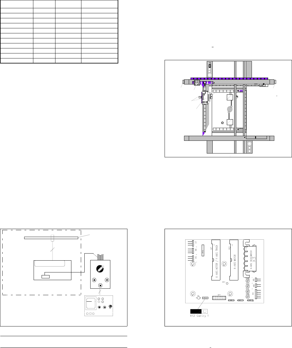
Fig. 10.4.1 Position of the boards to be measured Y0055 and Y0004
Key to Fig. 10.4.1
1) Large axis conversion board Y0004 2) Gluing heads
3) Small axis conversion board Y0055 4) Gantry conversion board Y 0053
5) Gluing head control board Y0054
➀
➁
➂
➃
➄
10 Siplace G automatic glue applicator SIPLACE 80S/80F/G Service Manual
Edition 06/98
10 - 62
Fig. 10.4.2 Basic test set-up
PLEASE NOTE
The protective earth in the mains plug of the oscilloscope must not be insulated or clamped.
● To measure the Y axis, connect the connecting cable of the tester measuring system to plug X11 on the
large axis conversion board Y0004 (see Fig. 10.4.3).
● To measure the X axis, connect the connecting cable of the tester measuring system to plug X 28 on the
small axis conversion board Y 0055 (see Fig. 10.4.4).
.....
Messsystem X - Y
Ah
X 11 / X 28
Spur A / B / RI
Platine Y0004 / Y0055
BNC - Leitung
Flachbandanschlusskabel
Siplace G
Auflösung des Massstabes:
01
1 Digit = 0,0025 mm
CH1 CH2
X
Y
Track signal tester
RI
Track
AB
Tracks A / B / RI
PC board Y0004 / Y0055
Scale resolution
1 Digit = 0.0025 mm
Flat ribbon conn. cable
Track signal tester
X-Y measurement system
SIPLACE 80S/80F/G Service Manual 10 Siplace G automatic glue applicator
Edition 06/98
10 - 63
Fig. 10.4.3 Large axis conversion board Y0004, PS 8
Key to Fig. 10.4.3
Test points X 11:
- X 11, 4/6 input of RSF 1,2 V
PP
+ 0.1V R 48: Amplitude of track A
- X 11, 5/7 output of amplifier 1.8 V
PP
R 33: Offset of track A
- X 11, 1/2/3 output of 5V gate, square-wave R 15: Amplitude of track B
- X 12: Jumper for counting direction R 29: Offset of track B
10 Siplace G automatic glue applicator SIPLACE 80S/80F/G Service Manual
Edition 06/98
10 - 64
Fig. 10.4.4 Small axis conversion board Y0055, ES 5
Key to Fig. 10.4.4
Test points X 28:
- X28, 4/6 RSF input, 1.2V
PP
(+ 0.1V)
- X28, 1/2/3 output of 5V gate, square-wave
- X28, 5/7 output of amplifier, 1.8V
PP
- X29: Place jumper for counting direction between PIN 1 and PIN 2
10.4.2 Adjusting the symmetry and amplification on the measuring sys-
tem
● Set the selector switch of the tester measuring system to "Oscilloscope cal".
● Connect channel 1 and 2 of your oscilloscope to the "Track A" and "Track B" BNC socket of the tester
measuring system.
● Set the voltage range of your oscilloscope to 0.2 V/Div. (see Table 10.4 - 1)
● Move the two beams so that they cover the center line of the screen.
X9 X1 3
X1 1
X2 8
X2 9
1
IC1
IC19
X15
X16
X17
R71
R69
R72
R70
R1
R2
R3
IC20
R73
R74
X8 X1 0 X12
X27 X14 X2 3
X24 X25 X2 6
X22 X21 X20 X19 X18
TP1
1
Amplitude
Offset
Amplitude
Offset
Spur A
Spur B
1
Amplitude
Offset
Amplitude
Offset
Track A
Track B
SIPLACE 80S/80F/G Service Manual 10 Siplace G automatic glue applicator
Edition 06/98
10 - 65
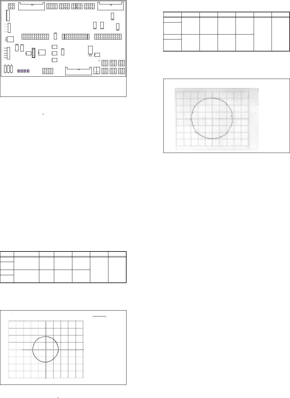
● Select X-Y mode on your oscilloscope.
● Move the light beam until it is exactly in the middle of the screen.
● Set the selector switch of the tester measuring system to "Sine-wave amplifier input"
● Manually move the gantry quickly backward and forward. The following image should appear on screen
(see Fig. 10.4.5):
Fig. 10.4.5 Signal at the sine-wave amplifier input, cannot be set electrically
Input Test point Signal Coupling Y deflection Trigger X deflection
CH1 Measuring
system
BNC socket
of tester
Track A DC 0.2 V/Div
X-Y mode
GND
CH2 Measuring
system BNC
socket of
tester
Track B DC 0.2V/Div
GND
Tab. 10.4 - 1 Parameters for setting the oscilloscope: Setting the track signals
Track setting in X / Y mode
Track A
CH2: 200 mV
Track B
10 Siplace G automatic glue applicator SIPLACE 80S/80F/G Service Manual
Edition 06/98
10 - 66
● Set the selector switch of the tester measuring system to "Oscilloscope cal".
● Set the voltage range of your oscilloscope to 0.5 V/Div. (see Table 10.4 - 2)
● Move the two beams so that they cover the center line of the screen.
● Select X-Y mode on your oscilloscope.
● Move the light beam until it is exactly in the middle of the screen.
● Set the selector switch of the tester measuring system to "Sine-wave amplifier output."
● Manually move the gantry quickly backward and forward.
● Use the "Offset" and "Amplification" potentiometers on the board concerned to move the circle on the
screen until the diameter is 1.8 V and its center is in the middle of the screen (see Fig. 10.4.6).
Fig. 10.4.6 Signal at the sine-wave amplifier output, can be set electrically
● If you cannot make the setting as described above, check the mechanical setting of the distance between
the scanning head and the track rule (0.4 mm +
0.05 mm).
❏
Input Test point Signal Coupling Y deflection Trigger X deflection
CH1 Measuring system,
BNC socket of
tester
Track A DC 0.5 V/Div
X-Y mode
GND
CH2 Measuring sys-
tem, BNC socket
of tester
Track B DC 0.5V/Div
GND
Tab. 10.4 - 2 Parameters for setting the oscilloscope
DATE : Mai
23/95
TIME : 13 : 35 : 15
Spur A
CH2: 500mV v.500mV
Spur B
Spureinstellung im X / Y - Betrieb
Track settings in the X / Y operation
Track A
CH2: 200 mV
Track B

SIPLACE 80S/F/G Service Manual 11 Control Unit
Edition 04/97
11 - I
Contents
Page
11 Control Unit
11.1 Replacing Modules. . . . . . . . . . . . . . . . . . . . . . . . . . . . . . . . . . . . . . . . . . . . . . . . . . . . . . .11 - 3
11.1.1 Auxiliary Materials and Equipment Required . . . . . . . . . . . . . . . . . . . . . . . . . . . . . . . . . . . . 11 - 3
11.1.2 Preparatory Work . . . . . . . . . . . . . . . . . . . . . . . . . . . . . . . . . . . . . . . . . . . . . . . . . . . . . . . . .11 - 3
11.1.3 Replacing the Machine Controllers M18. . . . . . . . . . . . . . . . . . . . . . . . . . . . . . . . . . . . . . . . 11 - 4
11.1.4 Replacing Station Computer M34. . . . . . . . . . . . . . . . . . . . . . . . . . . . . . . . . . . . . . . . . . . . . 11 - 5
11.1.5 Replacing the Hard Disk / Floppy Disk Board . . . . . . . . . . . . . . . . . . . . . . . . . . . . . . . . . . .11 - 6
11.2 Set-Up Configuration of the M34 Station Computer . . . . . . . . . . . . . . . . . . . . . . . . . . . . 11 - 7
11.2.1 Configuration Data . . . . . . . . . . . . . . . . . . . . . . . . . . . . . . . . . . . . . . . . . . . . . . . . . . . . . . . .11 - 7
11.2.1.1 Screen 1. . . . . . . . . . . . . . . . . . . . . . . . . . . . . . . . . . . . . . . . . . . . . . . . . . . . . . . . . . . . . . . . 11 - 7
11.2.1.2 Screen 2. . . . . . . . . . . . . . . . . . . . . . . . . . . . . . . . . . . . . . . . . . . . . . . . . . . . . . . . . . . . . . . . 11 - 8
11.2.1.3 Screen 3. . . . . . . . . . . . . . . . . . . . . . . . . . . . . . . . . . . . . . . . . . . . . . . . . . . . . . . . . . . . . . . . 11 - 8
11.3 Wrap Connections of the Station Computer . . . . . . . . . . . . . . . . . . . . . . . . . . . . . . . . . . 11 - 9
11.3.1 KSP-M34-A162 Station Computer . . . . . . . . . . . . . . . . . . . . . . . . . . . . . . . . . . . . . . . . . . . .11 - 9
11.3.2 IEC-Bus Module . . . . . . . . . . . . . . . . . . . . . . . . . . . . . . . . . . . . . . . . . . . . . . . . . . . . . . . . . .11 - 9
11.4 Wrap Connections of Machine Controller MC1 (left-hand side) . . . . . . . . . . . . . . . . . 11 - 10
11.4.1 KSP-M18-A16 C8451-A45-A52-X Machine Controller . . . . . . . . . . . . . . . . . . . . . . . . . . 11 - 10
11.5 Wrap Connections of Machine Controller MC2
(right-hand side, applies to 80S only). . . . . . . . . . . . . . . . . . . . . . . . . . . . . . . . . . . . . . . 11 - 11
11.5.1 KSP-M18-A16 C8451-A45-A51-X Machine Controller . . . . . . . . . . . . . . . . . . . . . . . . . . 11 - 11