80S-15贴片机.pdf - 第126页
5 Gantries SIPLACE 80 S/F/G Service Manual Edition 04/97 5 - 8 Fig. 5.2.1 X-axis motor - front view Key to Fig. 5.2.1. 1 Hexagon s ocket sc rew for mou nting m otor 2 Endless too thed bel t 3 Belt wheel 4 Deflect ion pul…

SIPLACE 80 S/F/G Service Manual 5 Gantries
Edition 04/97
5 - 7
5.2 Replacing the Drive Motor of the X Axis
5.2.1 Spare Parts, Auxiliary Materials and Equipment
–
1 motor for the x axis, complete, from item no. 00310954-01
–
2 cable ties
–
Belt tension measuring device, from item no. 00326015-01
5.2.2 Removal
NOTE
OOO
You should comply with the safety instructions given in .
●
Unplug the flat ribbon cable and the motor cable from the conversion board, large axis.
●
Remove the ribbon cable holder in a way that you can swing the entire cabling unit to one side.
●
You will find it easier to get at the motor unit if you first remove the large axis conversion board, if neces-
sary.
●
Unscrew and remove the hexagon socket screws which attach the motor to the flange.
●
Tilt the motor a little to one side and carefully pull the toothed belt off the motor pinion.
●
Pull the motor backwards and out of the flange.
NOTE
The motor is supplied as a complete unit consisting of the motor itself, the tachometer and motor pinion and
for this reason should also be replaced as a complete unit.
5 Gantries SIPLACE 80 S/F/G Service Manual
Edition 04/97
5 - 8
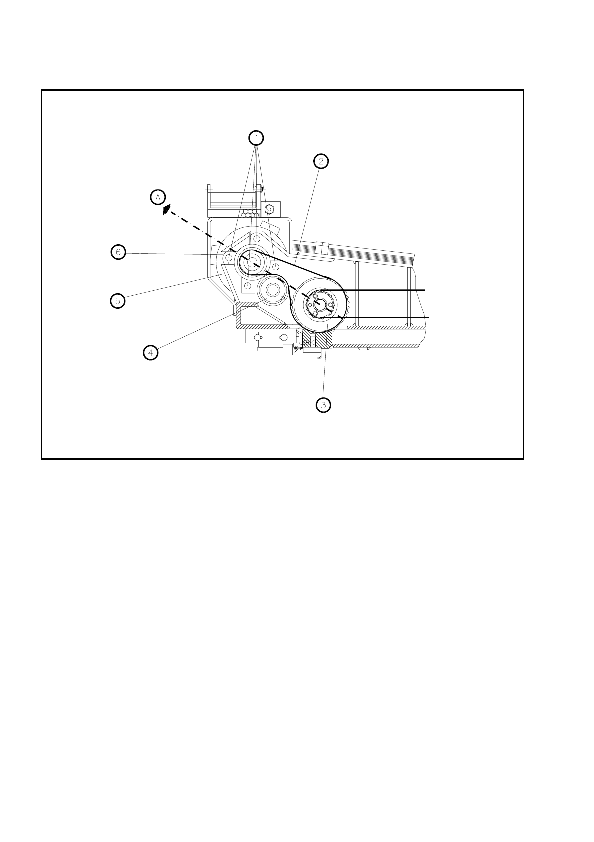
Fig. 5.2.1 X-axis motor - front view
Key to Fig. 5.2.1.
1 Hexagon socket screw for mounting motor
2 Endless toothed belt
3 Belt wheel
4 Deflection pulley
5 X-axis drive motor
6 Flange
A Direction of tension to tension the endless toothed belt
SIPLACE 80 S/F/G Service Manual 5 Gantries
Edition 04/97
5 - 9
5.2.3 Installation
●
Insert the new motor through the flange and pull the toothed belt carefully over the motor pinion.
●
Mount the motor using the four hexagon socket screws and pretension the toothed belt.
NOTE
Make sure that the connection cable will not be subjected to rubbing over the entire travel range of the gantry.
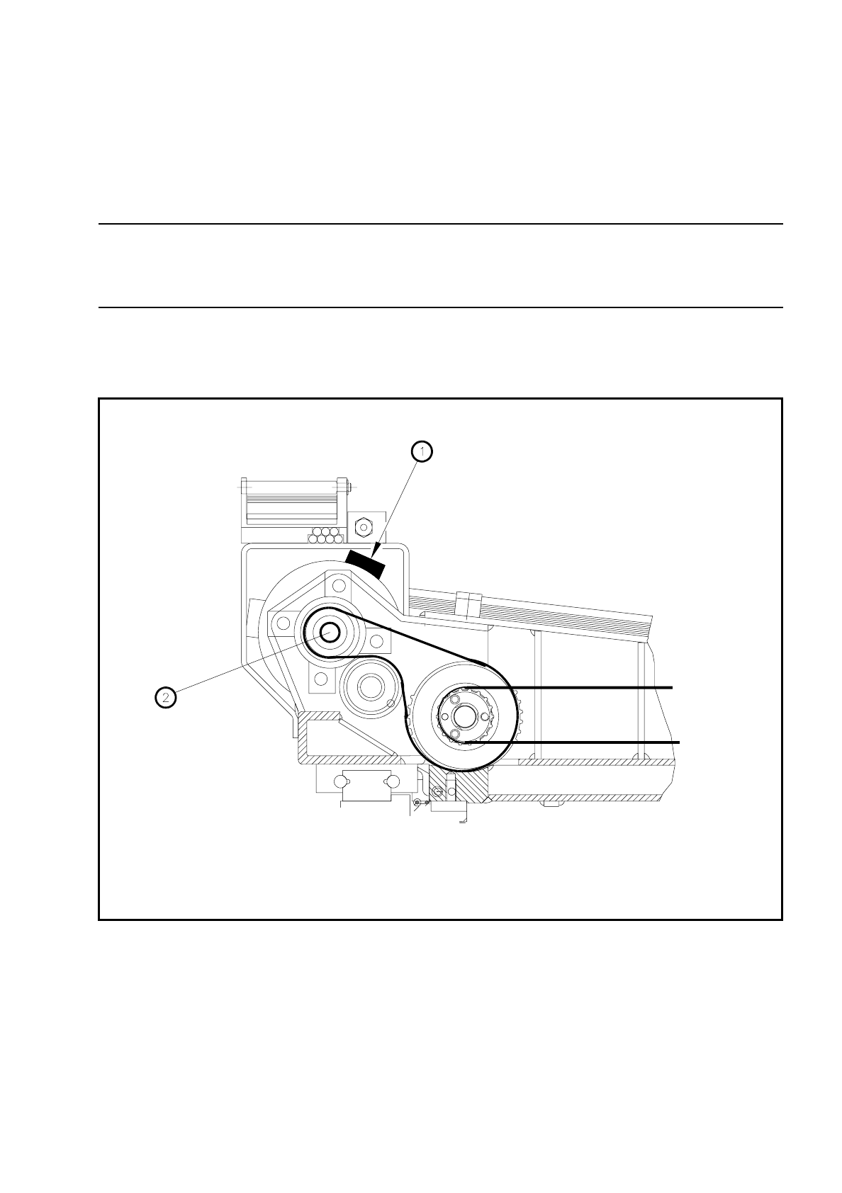
The motor connection cable must be in the 2 o’clock position as seen from the motor shaft (see Fig. 5.2.2).
●
Now adjust the tension of the toothed belt using Table 5.2 - 1 and tighten up the screws.
●
Plug the motor connection plug into the conversion board.
●
Attach the connection cable to the motor using the cable ties.
Fig. 5.2.2 Position of the x-motor connection cable
Key to Fig. 5.2.2.
1 2 o’clock position of the connection cable 2 Motor shaft