ntcat.pdf - 第256页
302 Consult “Precautions” page 327 before use, installation or service of MAC Valves.. Intrinsically Safe Valves What this means is that the intrinsically safe valves were tested against each atmosphere with up to 30 VDC…
301
Consult “Precautions” page 327 before use, installation or service of MAC Valves..
INTRINSICALLY SAFE CIRCUIT
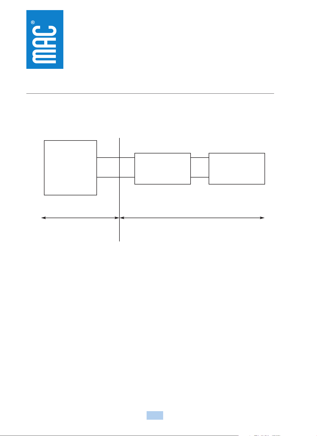
In order to use an intrinsically safe valve in a hazardous location, the installation must be in accordance with the following installation diagram :
Intrinsically Safe Valves
There are 3 basic parts to an intrinsically safe circuit :
1. FIELD DEVICE
This is defined as the device that will be used in the hazardous location. In this case, the field device will be the intrinsically safe valve.
2. ASSOCIATED APPARATUS
This will be an energy limiting device also known as a barrier.
3. FIELD WIRING
Wiring used to connect the two above devices.
When the MAC intrinsically safe valves were tested for approval, they were tested and approved for the following atmospheres.
Class I, II, III
Division 1
Groups ; A, B, C, D, E, F, G
under the following parameters :
Vmax : 30 VDC
Imax : 175 ma
Ci : 0
Li : 0
Hazardous Location
Class I, II & III
Division 1
Group A, B, C, D,
E, F & G
FMRC Approved Single
or Dual Channel Positive
Polarity Intrinsic Safety
Barriers
Approved for
Class I, II, & III
Division 1
Group A, B, C, D,
E, F & G
Vmax = 30 v
Imax = 175 ma
Ci = 0
Li = 0
Control Room
Equipment
+ Red
- Black
Non-Hazardous Location
MAC Valve
Associated Apparatus

302
Consult “Precautions” page 327 before use, installation or service of MAC Valves..
Intrinsically Safe Valves
What this means is that the intrinsically safe valves were tested against each atmosphere with up to 30 VDC and 175 ma of current across the solenoid and found to still be safe. The other
two parameters are values to indicate how much energy can be stored or created by the valve :
Ci : Internal capacitance of the solenoid.
This indicates how much energy the solenoid is capable of storing.
Li : Internal inductance of the solenoid.
This indicates the solenoid’s ability to create or increase energy beyond what is supplied.
When applying an intrinsically safe valve in a hazardous location, a proper barrier must first be selected. The barrier selection process must first take into account the parameters the valve
was approved for and compared in the following way :
• Vmax must be greater than or equal to Voc of the barrier.
Voc = Voltage open circuit or maximum allowed out of the barrier
• Imax must be greater than or equal to Isc of the barrier.
Isc = Current short circuit or the maximum current allowed out of the barrier
• Ci plus field wiring must be less than Ca of the barrier.
Ca = Allowed capacitance
• Li plus field wiring must be less than La of the barrier.
La = Allowed inductance
When properly combined, the barrier will never allow more energy to the intrinsically safe valve than what it was tested and approved for.
The following page can be used as your guide to help ask the right questions when working with an intrinsically safe circuit. Also included is a partial list of intrinsically safe barriers that have
been tested with the MAC intrinsically safe valves.
303
Consult “Precautions” page 327 before use, installation or service of MAC Valves..
Intrinsically Safe Valves
Approval : Factory Mutual Research 2X7A8.AX (3610)
Approved as intrinsically safe apparatus and associated apparatus for use in Class I, II, III - Division 1, Group : A, B, C, D, E, F & G.
Parameters : Vmax : 30 VDC
Imax : 175 ma
Ci : 0
Li : 0
Operating voltage greater than 11.5 volts
Coil resistance : Approximately 250 ohms
Current draw : 50 ma
Wattage : 0.6 watts
Circuit Check Lists :
• Is Vmax greater than or equal to Voc ?
• Is Imax greater than or equal to Isc ?
• Is Ci less than Ca ?
• Is Li less than La ?
• Is the barrier capable of handing 50 ma draw ?
• Is the internal resistance of the barrier 250 ohms or less ?
If all answers to the above questions are “yes” the barrier may be a good choice in combination with the MAC intrinsically safe valve.
To calculate voltage across the solenoid, plug values into the following equations :
ITOTAL =
I
TOTAL
=
SUPPLY VOLTAGE
= Plug ITOTAL in below
Plug I
TOTAL in below
250 + BARRIER RESISTANCE
Voltage at Solenoid = I
TOTAL
x 250 ohms = volts
Voltage Voltage
Manufacturer Model # Barrier Res. w/o Light w/Light Groups Type
Turck MK72-S01-EX 11.2 v 10.2 v* A-G T.I.B.
Crouse-Hinds SB19140-M2410 13.2 v 12.6 v C-G Zener
IMO Industries (Gems Sensors) 114072 234 OHMS 12.0 v 11.4 v C-G Zener
Pepperl & Fuchs KHZ-922/EX-1 270 OHMS 11.6 v 11.06 v A-G Zener
KHZ-922/EX-2 270 OHMS 11.6 v 11.06 v A-G Zener
KHZ-922/EX-3 270 OHMS 11.6 v 11.06 v A-G Zener
Stahl 9001/01-280-165-10 13.5 v 12.9 v C-G Zener
9351/10-14-10 80 OHMS 13.7 v 13.4 v A-G T.I.B.
Ronan X57-229P 200 OHMS 12.7 v 12.05 v C-G Zener
Measurement Technology MTL728P+ 250 OHMS 11.9 v 11.4 v A-G Zener
MTL3022 15.0 v 14.5 v C-G T.I.B.
Above data is based on a 24 v DC supply voltage to the input of the barrier. A 12 v DC, 243 OHM, .6 watt intrinsically safe solenoid is used. The measurement with light is an LED with a
current limiting resistor.
Groups indicate what atmosphere the barrier has been approved for. All MAC intrinsically safe valves have been approved for Class I, II and III, Division 1, Groups A, B, C, D, E, F and G
indoor hazardous locations.
T.I.B. = Transformer Isolated Barrier
* = Not a recommended combination