ntcat.pdf - 第274页
324 Consult “Precautions” page 327 before use, installation or service of MAC Valves.. Technical Info MAC’s PATENDED LATCHING SOLENOID – Eliminates one Solenoid, Simplifies Wiring, Reduces Package Size MAC’s latching sol…

323
Consult “Precautions” page 327 before use, installation or service of MAC Valves..
Section 7
Supplemental technical information
324
Consult “Precautions” page 327 before use, installation or service of MAC Valves..
Technical Info
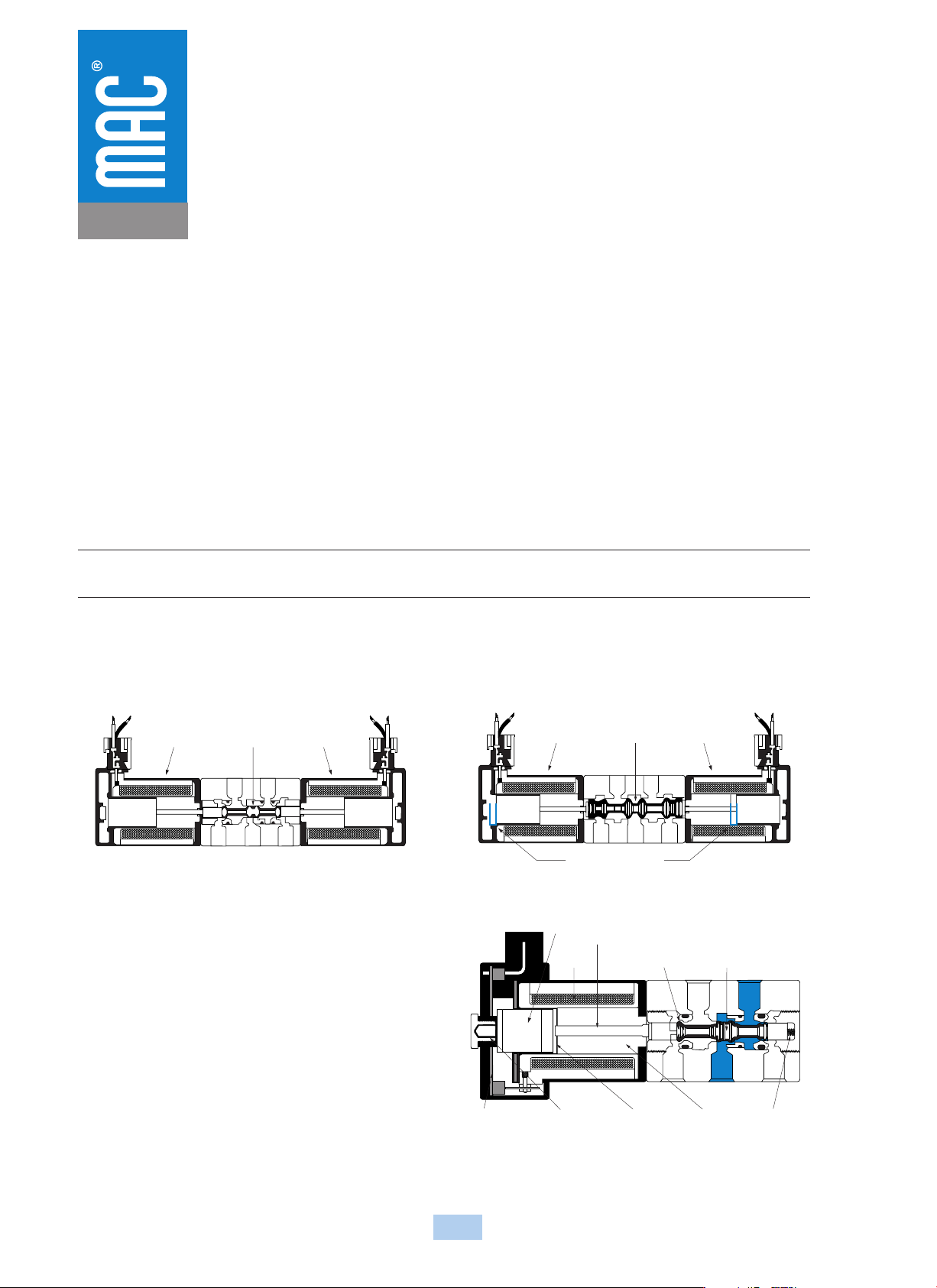
MAC’s PATENDED LATCHING SOLENOID – Eliminates one Solenoid, Simplifies Wiring, Reduces Package Size
MAC’s latching solenoid technology provides the function of a double solenoid operated valve utilizing only one solenoid.
Typical 2 position direct operated double solenoid valves use two solenoids with spool/bore technology. When the power is removed
from either solenoid, the spool position and valve function is maintained.
With direct acting solenoid valves, poppets with their inherent short strokes are not typically used as they cannot maintain sealing
position when both solenoids are deenergized. As a consequence, longer stroking spool type solenoid valves are used which results in
lower shifting forces. MAC’s latching solenoid technology eliminates the sealing issue with poppets when no electrical signal is
applied, by maintaining solenoid force, ensuring adequate sealing, while using short stroking poppets resulting in high shifting forces.
MAC’s latching solenoid only requires one solenoid and correspondingly one plug-in and one conduit wireway verus two for
conventional double solenoid valve, saving space, weight and cost. An added benefit of a latching solenoid valve when mounted on
a circuit bar is the additional option of side cylinder ports.
HOW IT WORKS
Unlike a spool and bore valve, a poppet valve requires that a force be continuously applied to either end of the poppet to ensure that proper sealing occurs. If
another solenoid was simply added to the valve to create a double solenoid valve, power would need to be constantly applied to either solenoid for the valve to
function properly (see Figure 1). If the poppet valve is converted to a spool and bore type valve design, the longer stroke of the spool and solenoid would result
in lower net shifting forces (see Figure 2), compromising the valves shifting reliability.
The latching solenoid overcomes these problems by introducing a powerful
permanent magnet armature assembly which magnetically latches itself to
the pole piece and in turn keeps the poppet sealed against the conical
seats when the power is removed from the solenoid. To shift the poppet in
the opposite direction, the polarity of the voltage applied to the solenoid
leads is reversed and the attractive force between the permanent magnet
armature assembly and the pole piece is reduced. The return spring in the
valve then shifts the poppet to its other sealing position and the permanent
magnet armature assembly is then magnetically attracted to the upper latch.
The upper latch prevents the permanent magnet armature assembly from
attracting itself back to the pole piece when the voltage is removed.
Reversing the polarity again to the solenoid lead wires will create a
powerful attractive force between the permanent magnet armature assembly
and the pole piece and away from the upper latch which will
correspondingly move the poppet to the other shifted position.
Solenoid Poppet Solenoid
Solenoid Spool Solenoid
Long Solenoid Stroke
Cyl A
Exh A Exh BInlet
Cyl B
A
rma
t
ure
Coil
Push Pin
Conical Seat
(cushioning)
Poppet
Circuit Board Upper Latch Lower Latch Pole Piece Valve Spring
Figure 1 : Double Solenoid Poppet
Figure 2 : Double Solenoid Spool Design
Figure 3 : Latching Solenoid Design

325
Consult “Precautions” page 327 before use, installation or service of MAC Valves..
Technical Info
+
-
SOLENOID "A"
+
-
SOLENOID "B"
WIRING SCHEMATIC FOR
DOUBLE SOLENOID
Figure 4 : Conventional Double Solenoid
WIRING INSTRUCTIONS AND OPTIONS
As shown in Figure 4, a conventional double solenoid valve requires that the pair of lead wires from each solenoid be wired to an appropriate voltage source,
MAC's latching solenoid technology has the option of being wired in one of the three (3) currently available methods.
FOUR WIRE
As shown in Figure 5, the four wire method enables
the coil to be wired as if it were a conventional
double solenoid. By connecting the yellow lead wire
to positive voltage and the yellow lead wire with
black stripe to negative, the valve will be open to
cylinder port”A”. When positive voltage is supplied to
the red lead wire and negative to the red lead with a
black stripe, the valve will now be open to cylinder
port”B”. Since the negative red and yellow lead wires
are internally connected together, the supply voltage
for each pair of yellow and red lead wires must be
isolated from the other pair (see diagram). Also,
power must not be applied to all four leads
simultaneously or a short circuit condition will occur
possibly damaging the voltage source.
THREE WIRE
Unlike the two wire method ( see Figure 7) which
requires the user to provide the polarity switching
circuitry, the three wire method incorporates the
polarity switching circuitry within the solenoid
enclosure ( see Figure 6). The black lead wire
provided must be connected to positive and is used
as a common. When negative voltage is supplied
to the yellow lead wire with a black stripe the valve
will be open to cylinder port ”A”. When the
negative voltage is removed from the yellow lead
wire with the black stripe and supplied to the red
lead wire with a black stripe, the valve will now be
open to cylinder port “B”. Applying voltage to all
three wires simultaneously or with the wrong
polarity will cause permanent damage to the
switching circuitry in the solenoid cover, and the
valve won’t work.
(+) POS IN A - Yellow
(+) POS IN B - Red
(-) NEG IN A
Yellow/W/Black Stripe
(-) NEG IN B
Red/W/Black Stripe
• No circuit board needed
• Wired as conventional double
• Must isolate pairs of red and
yellow wires from each other
Red/Black Stripe
Red
Yellow
Yellow/Black Stripe
4 WIRE SCHEMATIC FOR LATCHING
+
-
YELLOW W/BLACK STRIPE
RED W/BLACK STRIPE
BLACK
• Switching done on circuit
board within valve
• Do not apply power to all
3 wires simultaneously
Red/Black Stripe (-)
Neg In Cyl B Operation
Black (+)
Positive Common
Yellow/Black Stripe (-)
Neg In Cyl A Operation
3 WIRE SCHEMATIC FOR LATCHING
(+) IN A
(-) IN B
(+) COMMON
Figure 5 : Four Wire Latching
Figure 6 : Three Wire Latching