ntcat.pdf - 第260页
307 Consult “Precautions” page 327 before use, installation or service of MAC Valves.. Section 6 Options
305
Consult “Precautions” page 327 before use, installation or service of MAC Valves..
Series
92
Intrinsically Safe Valves
HOW TO ORDER
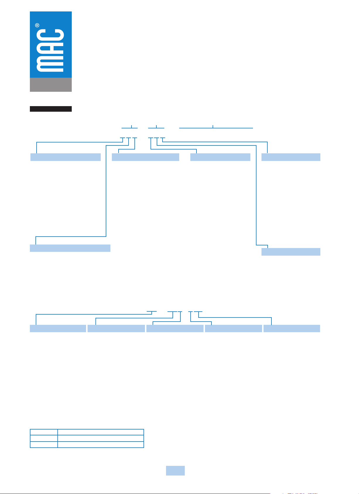
92B - XXX - XXX - (XX - DXXX - XXX)
BODY
OPTIONS
BASE
OPTIONS
PILOT
VALVE
SEE BELOW
BODY TYPE & EXHAUST OPTIONS
0
Base only
A
Plug-in Standard Exhaust
B*
Non Plug-in with Standard Exhaust
* Use with body electrical option A only
BODY ELECTRICAL OPTIONS
0
Base only
A
No ligth in top
B
With ligth
VALVE FUNCTION
0
Base only
A
Single Operator-Single Pressure
B
Double Operator-Single Pressure
C
Single Operator-Dual Pressure
D
Double Operator -Dual Pressure
E
3 Position Closed Center
F
3 Position Open Center
G
3 Position Single Pressure
Pressure Center
Spool with Memory Spring
L
Single Operator-Single Pressure
N
Single Operator-Dual Pressure
INDIV. BASE CONFIG.
0
Basic Valve
A
Side Ports
B
Bottom Ports (1/8” only)
C
Side & Bottom Ports
(1/8” only)
D
Side in & exhaust Bottom
cylinders (1/8” only)
PORT SIZE - THREAD TYPE
0
Basic Valve
A
1/8” NPTF
B
1/4” NPTF
C
3/8” NPTF
D
1/8” BSPPL
E
1/4” BSPPL
F
3/8” BSPPL
G
1/8” BSPTR
H
1/4” BSPTR
J
3/8” BSPTR
INT. OR EXT. PILOT
0
Basic Valve
Plug-in Internal Pilot Models
A
No light in base
B
With single light in base
C
With double light in base
Plug-in External Pilot Models
D
No light in base
E
With single light in base
F
With double light in base
Non plug-in
G
Internal Pilot
H
External Pilot
If lights are in top body cover, use
option A or D
PILOT VALVE OPTIONS
XX - DXXX - XXX
XX
PILOT EXHAUST
DM
Muffled exhaust
XX
DC VOLTAGE
FR
12 VDC (0.6 W)
X
LEAD WIRE LENGTH
--Plug-in Valve/Base--
P
Plug-in
1
18”
4
48”
2
24”
5
72”
3
36”
6
96”
--Non Plug-in Valve/Base--
O
No wires*
A
18”
E
72”
B
24”
F
96”
C
36”
J
6”**
D
48”
*Used only with BM & BG
electrical connection
** Lead wire length for external
plug-in connectors must be “J”
X
MANUAL OPERATOR
0
No manual operator
1
Recessed Non-locking
operator
2
Recessed Locking operator
3
Non-locking Extended
operator
4
Locking Extended
operator
XX
ELECTRICAL CONN.
--Non Plug-in Valve/Base--
BA
Grommet
BM
Flying leads
BG
Flying leads with ground
CA
Conduit 1/2" NPS
CM
Metal
Conduit 1/2" NPS
CN
Metal
Conduit with
ground1/2" NPS
--Plug-in Valve/Base--
DM
Plug-in
DG
Plug-in with ground
--External Plug-in--
JB
Rectangular plug-in
JM
Rectangular male only
KA
Mini plug-in
KJ
Mini plug-in male only
HOW TO ORDER 92 SERIES FLOW CONTROL MODULE*
NOTE: If a flow control assembly is used with the dual
pressure regulator option, only the flow control on the
“B” end is functional. (Controls both cylinder ports.)
NOTE: Consult the general catalog for regulator and
circuit bar ordering information.
FC 92C-AA
FC 92C-BA
FC 92C-CA
Plug-in flow control assembly single solenoid
Plug-in flow control assembly double solenoid
Non plug-in flow control assembly
*If flow control module is to be installed between valve and base or valve and manifold at the factory,
add -9 after the flow control model number, i.e., FC92C-AA-9. The flow control model number
should follow the valve model number on which it is to be installed.

307
Consult “Precautions” page 327 before use, installation or service of MAC Valves..
Section 6
Options

309
Consult “Precautions” page 327 before use, installation or service of MAC Valves..
OPTIONS
Codification table for voltages / Manual operator / Electrical connection
- Pilot operated valves 52, 67, 92, 93, 400, ISO1, ISO2, ISO3 Series
-DM- D XX X-X XX
1 2 3 4
VALVE CODE
®
OPTIONS AVAILABLE FOR