ntcat.pdf - 第90页
OPERATIONAL BENEFITS Direct solenoid and solenoid pilot operated valves HOW TO ORDER 115 Consult “Precautions” page 327 before use, installation or service of MAC Valves.. 36 32 37 38 33 34 52 67 46 44 47 42 400 48 92 93…
67.0
TYP.(2) HOLES
4.30 DIA.
APPROX
APPROX
D
5.028.10
38.1
A
C
B
35.10
11.0
73.1
54.6
E
H
F
G
12
14
G
-
+
1
24
53
14
12
18
18
10 0
%
10 0
%
10 0
%
10 0
%
MONTHS
WARRANTY
OF
PRODUCTION
TESTED
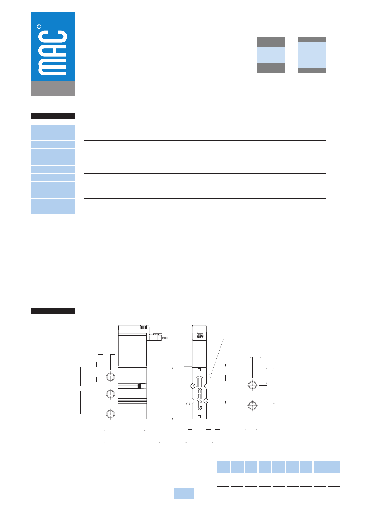
DIMENSIONS
TECHNICAL DATA
Dimensions shown are metric (mm)
114
Consult “Precautions” page 327 before use, installation or service of MAC Valves..
Series
47
Fluid :
Pressure range :
Lubrication :
Filtration :
Temperature range :
Flow :
Coil :
Voltage range :
Power :
Response times :
(with 5.2 W coil)
Compressed air, vacuum, inert gases
Vacuum to 120 PSI
Not required, if used select a medium aniline point lubricant (between 180°F and 210°F)
40 µ
0°F to 120°F (-18°C to +50°C)
5.2W : (0.50 C
v
) – 2.4W : (0.35 C
v
) – 1.0W : (0.30 C
v
)
Class A wire (#22 AWG x 18), continuous duty
-15% to +10% of nominal voltage
5.2W – 2.4W – 1.0W
Energize : 17.4 ms
De-energize : 3.8 ms
• BSPP threads
• Pressure seal body to base: 16628 • Mounting screw (x2): 35043
• Flow control assembly (x2): N-04001
Options :
Spare parts :
DIM.
1/8"
1/4"
A
8.0
9.5
B
22.9
24.0
C
48.6
48.8
D
19.05
23.0
E
9.5
12.5
F
12.5
12.8
G
34.2
34.2
H
59.0
57.2
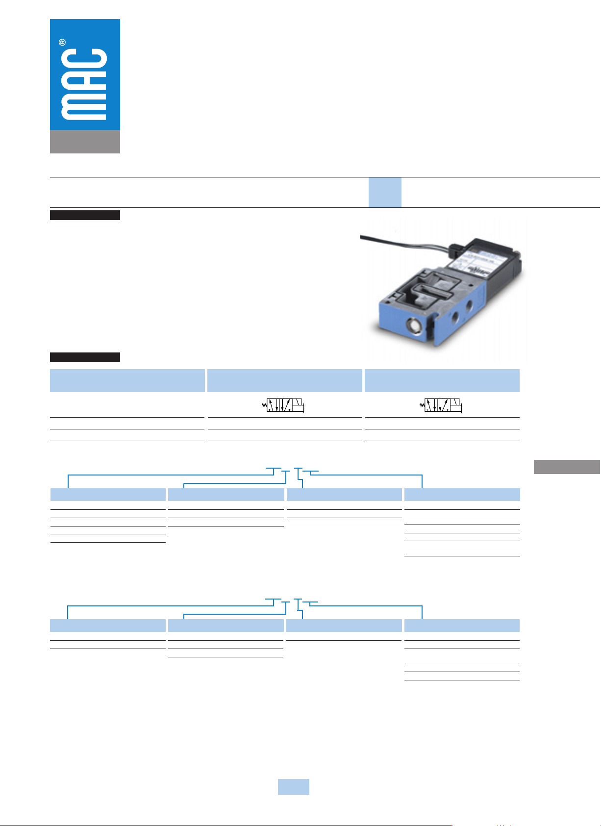
OPERATIONAL BENEFITS
Direct solenoid and solenoid pilot operated valves
HOW TO ORDER
115
Consult “Precautions” page 327 before use, installation or service of MAC Valves..
36
32
37
38
33
34
52
67
46
44
47
42
400
48
92
93
ISO 1
ISO 2
ISO 3
69
48P
ISO 01
ISO 02
Series
47
Function Port size Flow (Max) Manifold Mounting Series
5/2 1/8” - 1/4” 0.5 C
v
Stacking
1. Short stroke solenoid produces high
energization shifting force.
2. High force return spring due to high force
solenoid maximizes both energization and
de-energization shifting forces.
3. Built-in wear compensation – valve stroke is
shorter than solenoid stroke.
4. Four bonded balanced poppets on a one-
piece valve stem.
5. End poppets seal first on conical seats and
cushion inlet poppet, eliminating cutting.
6. Exhaust seals are not under inlet pressure thus
reducing friction.
7. Integral non-rising flow controls available on
inline models.
8. Short stroking balanced poppet allows for
direct solenoid operation with high shifting
forces, minimized friction, fast response and
high flow in a small package.
Port size
1/8” NPTF
1/4” NPTF
Without flow controls
47A-SA0-H
XXX-XXX
47A-SB0-H
XXX-XXX
With flow controls
47A-TA0-H
XXX-XXX
47A-TB0-H
XXX-XXX
3
4
1
2
5
1412
3
4
1
2
5
1412
H
XXX
-
XXX
*
SOLENOID OPERATOR
®
Voltage
DA
24 VDC (5.2W)
DB
24 VDC (2.4W)
DC
24 VDC (1.8W)
DD
24 VDC (1.0W)
AA
120 VAC (6.7W)
Lead Wire length
A
18”
B
24”
C
36”
Manual operator
1
Non-locking recessed
2
Locking recessed
Electrical connection
MA
Plug-in wire assembly
MC
Plug-in wire assembly with
light
BA
Flying leads
BC
Flying leads with light
MT
Plug-in wire assembly with
rectifier & light
XX X X XX
* Other options available, see page 319.
End plate kit required: M-47013-01 (1/4“ NPTF).
* Other options available, see page 315.
Note: AC voltage requires connector with rectifier.
L
XXX
-
XXX
*
LATCHING OPERATOR
®
Voltage
DA
24 VDC (5.2W)
DF
12 VDC (5.2W)
Lead Wire length
A
18”
B
24”
C
36”
Manual operator
0
No operator
Electrical connection
BA
2 Wire Flying leads
BJ
4 Wire Flying leads
LA
3 Wire Plug-in
(Polarity switching cover)
MA
2 Wire Plug-in
ME
4 Wire Plug-in
XX X X XX
4
2
2
44
2
95.0
TYP.
Ø 6.3 THRU.
TYP.
TYP.
30.7
5.3
TYP.
TYP.
TYP.
117.1
18.9
30.3
59.5
46.0
15.8
TYP.
Ø 6.3 THRU.
TYP.
TYP.
5.3
14.8
12
14
12
14
12
14
31
AUCKLAND,N.Z.
LIEGE,BELGIUM
WATTS
MODIF.
WIXOM,MI.,USA
ELECTRICAL
MODEL
13
TYP.
B
A
19.0
18
18
10 0
%
10 0
%
10 0
%
10 0
%
MONTHS
WARRANTY
OF
PRODUCTION
TESTED
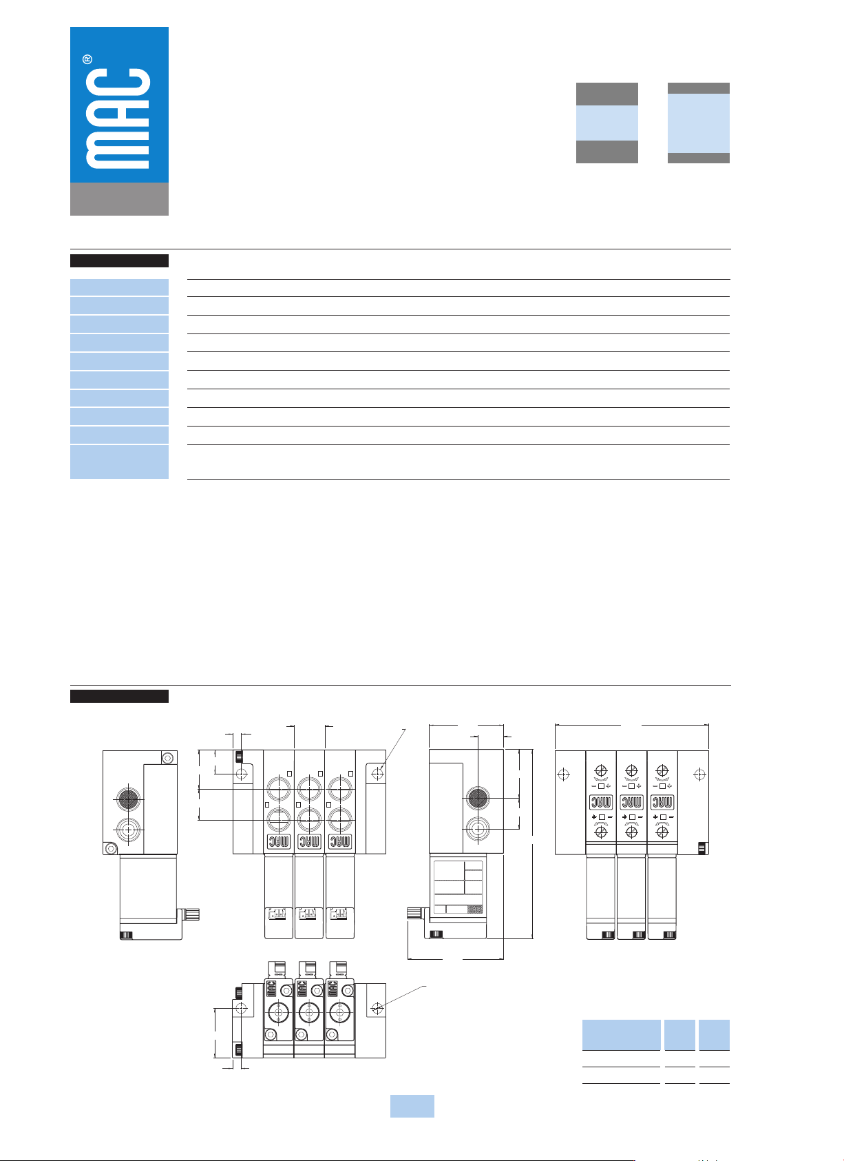
DIMENSIONS
TECHNICAL DATA
Dimensions shown are metric (mm)
116
Consult “Precautions” page 327 before use, installation or service of MAC Valves..
Series
47
Fluid :
Pressure range :
Lubrication :
Filtration :
Temperature range :
Flow :
Coil :
Voltage range :
Power :
Response times :
(with 5.2 W coil)
Compressed air, vacuum, inert gases
Vacuum to 120 PSI
Not required, if used select a medium aniline point lubricant (between 180°F and 210°F)
40 µ
0°F to 120°F (-18°C to +50°C)
5.2W : (0.50 C
v
) – 2.4W : (0.35 C
v
) – 1.0W : (0.30 C
v
)
Class A wires (#22 AWG x 18), continuous duty
-15% to +10% of nominal voltage
5.2W – 2.4W – 1.0W
Energize : 17.4 ms
De-energize : 3.8 ms
• BSPP threads
• Inlet isolator: 28451 • Exhaust isolator: N-47009 • Tie Rod (x2): 79057
Options :
Spare parts :
Dim
1/8”
1/4”
A
22.8
24.2
B
18.4
19