ntcat.pdf - 第273页
323 Consult “Precautions” page 327 before use, installation or service of MAC Valves.. Section 7 Supplemental technical information

322
Consult “Precautions” page 327 before use, installation or service of MAC Valves..
OPTIONS
1. VOLTAGE
R-XX X-X XX
VOLTAGE
DA
24 VDC (0.5W)
DB
24 VDC (1.0W)
DC
24 VDC (1.8W)
DD
24 VDC (2.5W)
DE
24 VDC (3.0W)
DF
24 VDC (4.0W)
DG
12 VDC (0.5W)
DH
12 VDC (1.0W)
DJ
12 VDC (1.8W)
DK
12 VDC (2.5W)
DL
12 VDC (3.0W)
DM
12 VDC (4.0W)
EA*
24 VDC (60W)
EB*
24 VDC (90W)
EC*
24 VDC (230W)
2. WIRE LENGTH (all series)
R-XX X-X XX
WIRE LENGTH
0**
No lead wire
A
18"
B
24"
C
36"
D
48"
E
72"
F
96"
G
120"
H
144"
3. MANUAL OPERATOR
R-XX X-X XX
MANUAL OPERATOR
0
No operator
1
Non-locking recessed
3
Non-locking extended
4. ELECTRICAL CONNECTOR
R-XX X-X XX
NON PLUG-IN
BA
Flying leads
BB
Flying leads with LED
BC
Flying leads with MOV
BD
Flying leads with LED and MOV
RA
Mini JAC solenoid plug-in
RB
Mini JAC solenoid plug-in with LED
RC
Mini JAC solenoid plug-in with MOV
RD
Mini JAC solenoid plug-in with LED and MOV
TA
JST solenoid plug-in
TB
JST solenoid plug-in with LED
TC
JST solenoid plug-in with MOV
TD
JST solenoid plug-in with LED and MOV
*MOD numbers required for these voltages (consult factory) ** Not available for flying leads connector

323
Consult “Precautions” page 327 before use, installation or service of MAC Valves..
Section 7
Supplemental technical information
324
Consult “Precautions” page 327 before use, installation or service of MAC Valves..
Technical Info
MAC’s PATENDED LATCHING SOLENOID – Eliminates one Solenoid, Simplifies Wiring, Reduces Package Size
MAC’s latching solenoid technology provides the function of a double solenoid operated valve utilizing only one solenoid.
Typical 2 position direct operated double solenoid valves use two solenoids with spool/bore technology. When the power is removed
from either solenoid, the spool position and valve function is maintained.
With direct acting solenoid valves, poppets with their inherent short strokes are not typically used as they cannot maintain sealing
position when both solenoids are deenergized. As a consequence, longer stroking spool type solenoid valves are used which results in
lower shifting forces. MAC’s latching solenoid technology eliminates the sealing issue with poppets when no electrical signal is
applied, by maintaining solenoid force, ensuring adequate sealing, while using short stroking poppets resulting in high shifting forces.
MAC’s latching solenoid only requires one solenoid and correspondingly one plug-in and one conduit wireway verus two for
conventional double solenoid valve, saving space, weight and cost. An added benefit of a latching solenoid valve when mounted on
a circuit bar is the additional option of side cylinder ports.
HOW IT WORKS
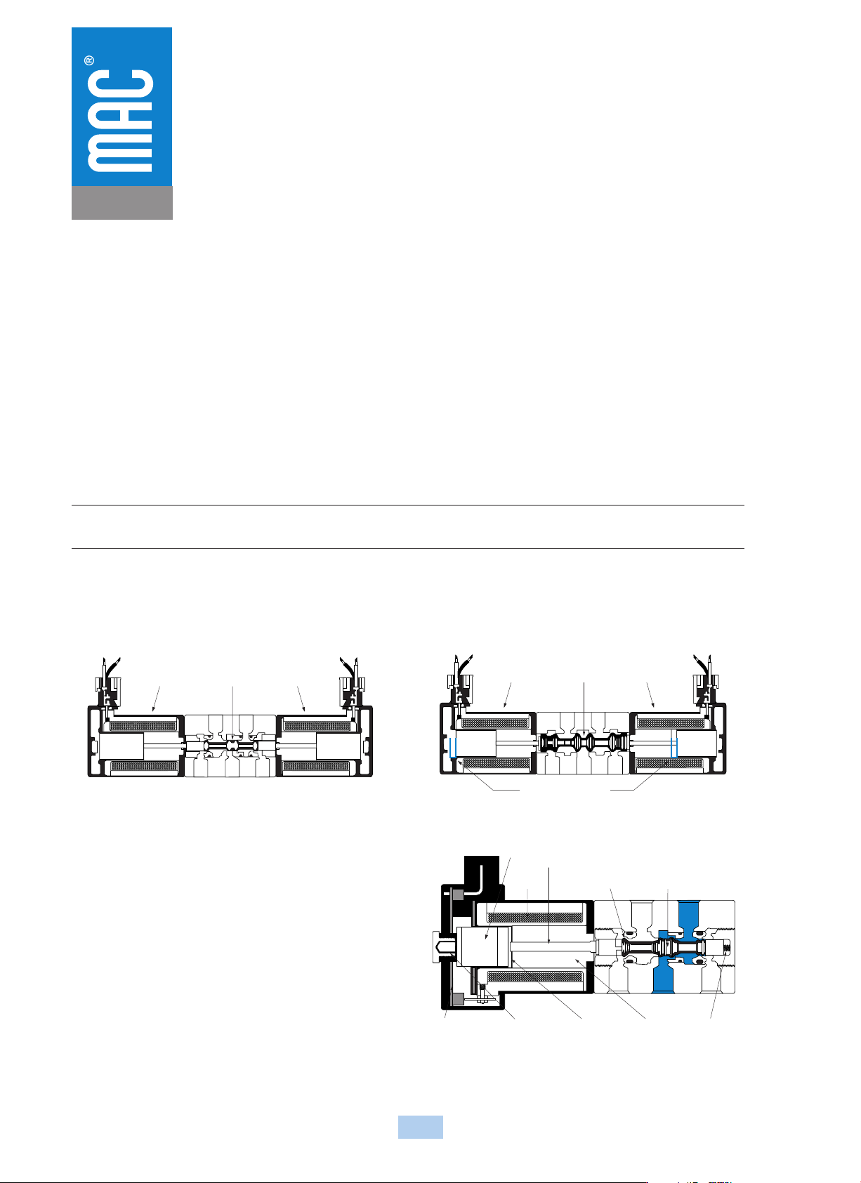
Unlike a spool and bore valve, a poppet valve requires that a force be continuously applied to either end of the poppet to ensure that proper sealing occurs. If
another solenoid was simply added to the valve to create a double solenoid valve, power would need to be constantly applied to either solenoid for the valve to
function properly (see Figure 1). If the poppet valve is converted to a spool and bore type valve design, the longer stroke of the spool and solenoid would result
in lower net shifting forces (see Figure 2), compromising the valves shifting reliability.
The latching solenoid overcomes these problems by introducing a powerful
permanent magnet armature assembly which magnetically latches itself to
the pole piece and in turn keeps the poppet sealed against the conical
seats when the power is removed from the solenoid. To shift the poppet in
the opposite direction, the polarity of the voltage applied to the solenoid
leads is reversed and the attractive force between the permanent magnet
armature assembly and the pole piece is reduced. The return spring in the
valve then shifts the poppet to its other sealing position and the permanent
magnet armature assembly is then magnetically attracted to the upper latch.
The upper latch prevents the permanent magnet armature assembly from
attracting itself back to the pole piece when the voltage is removed.
Reversing the polarity again to the solenoid lead wires will create a
powerful attractive force between the permanent magnet armature assembly
and the pole piece and away from the upper latch which will
correspondingly move the poppet to the other shifted position.
Solenoid Poppet Solenoid
Solenoid Spool Solenoid
Long Solenoid Stroke
Cyl A
Exh A Exh BInlet
Cyl B
A
rma
t
ure
Coil
Push Pin
Conical Seat
(cushioning)
Poppet
Circuit Board Upper Latch Lower Latch Pole Piece Valve Spring
Figure 1 : Double Solenoid Poppet
Figure 2 : Double Solenoid Spool Design
Figure 3 : Latching Solenoid Design