ntcat.pdf - 第258页
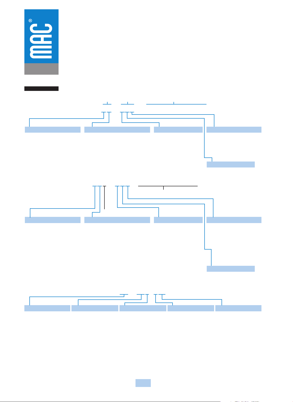
4XXA - XXX - XX - DXXX - XXX 304 Consult “Precautions” page 327 before use, installation or service of MAC Valves.. Series 52-400 Intrinsically Safe Valves HOW TO ORDER 52A - XX - XXX - (XX - DXXX - XXX) BODY OPTIONS BAS…
303
Consult “Precautions” page 327 before use, installation or service of MAC Valves..
Intrinsically Safe Valves
Approval : Factory Mutual Research 2X7A8.AX (3610)
Approved as intrinsically safe apparatus and associated apparatus for use in Class I, II, III - Division 1, Group : A, B, C, D, E, F & G.
Parameters : Vmax : 30 VDC
Imax : 175 ma
Ci : 0
Li : 0
Operating voltage greater than 11.5 volts
Coil resistance : Approximately 250 ohms
Current draw : 50 ma
Wattage : 0.6 watts
Circuit Check Lists :
• Is Vmax greater than or equal to Voc ?
• Is Imax greater than or equal to Isc ?
• Is Ci less than Ca ?
• Is Li less than La ?
• Is the barrier capable of handing 50 ma draw ?
• Is the internal resistance of the barrier 250 ohms or less ?
If all answers to the above questions are “yes” the barrier may be a good choice in combination with the MAC intrinsically safe valve.
To calculate voltage across the solenoid, plug values into the following equations :
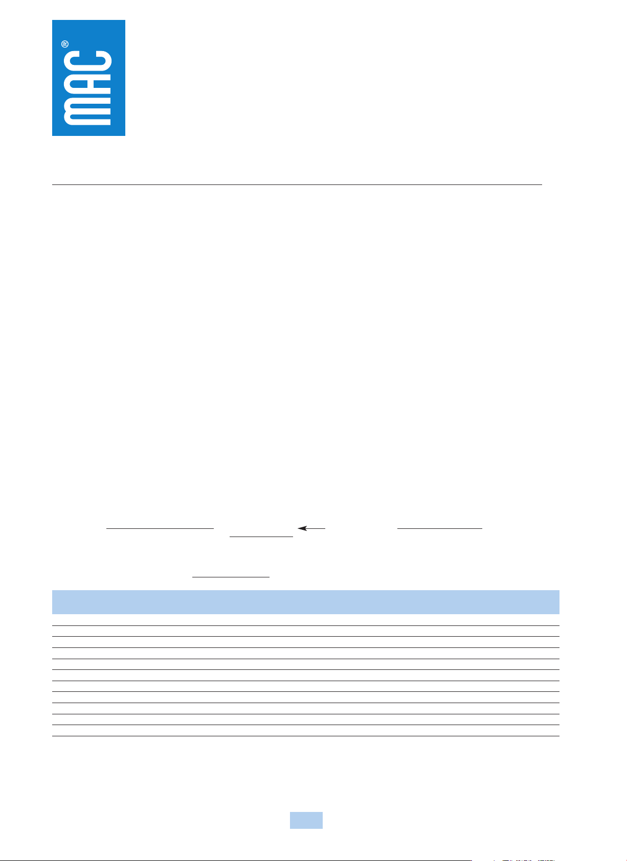
ITOTAL =
I
TOTAL
=
SUPPLY VOLTAGE
= Plug ITOTAL in below
Plug I
TOTAL in below
250 + BARRIER RESISTANCE
Voltage at Solenoid = I
TOTAL
x 250 ohms = volts
Voltage Voltage
Manufacturer Model # Barrier Res. w/o Light w/Light Groups Type
Turck MK72-S01-EX 11.2 v 10.2 v* A-G T.I.B.
Crouse-Hinds SB19140-M2410 13.2 v 12.6 v C-G Zener
IMO Industries (Gems Sensors) 114072 234 OHMS 12.0 v 11.4 v C-G Zener
Pepperl & Fuchs KHZ-922/EX-1 270 OHMS 11.6 v 11.06 v A-G Zener
KHZ-922/EX-2 270 OHMS 11.6 v 11.06 v A-G Zener
KHZ-922/EX-3 270 OHMS 11.6 v 11.06 v A-G Zener
Stahl 9001/01-280-165-10 13.5 v 12.9 v C-G Zener
9351/10-14-10 80 OHMS 13.7 v 13.4 v A-G T.I.B.
Ronan X57-229P 200 OHMS 12.7 v 12.05 v C-G Zener
Measurement Technology MTL728P+ 250 OHMS 11.9 v 11.4 v A-G Zener
MTL3022 15.0 v 14.5 v C-G T.I.B.
Above data is based on a 24 v DC supply voltage to the input of the barrier. A 12 v DC, 243 OHM, .6 watt intrinsically safe solenoid is used. The measurement with light is an LED with a
current limiting resistor.
Groups indicate what atmosphere the barrier has been approved for. All MAC intrinsically safe valves have been approved for Class I, II and III, Division 1, Groups A, B, C, D, E, F and G
indoor hazardous locations.
T.I.B. = Transformer Isolated Barrier
* = Not a recommended combination
4XXA - XXX - XX - DXXX - XXX
304
Consult “Precautions” page 327 before use, installation or service of MAC Valves..
Series
52-400
Intrinsically Safe Valves
HOW TO ORDER
52A - XX - XXX - (XX - DXXX - XXX)
BODY
OPTIONS
BASE
OPTIONS
PILOT
VALVE
BODY OPTIONS
1
Inline 3 port
3
Manifold body
4
Inline 3 port with memory spring
6
Manifold body with memory spring
INT. OR EXT. PILOT
A
Internal Pilot
B
External Pilot-For inline
bodies only
C
Common External Pilot for
manifold bodies only
SPOOL TYPE
1
Single Operator N.C. Main
2
Double Operator N.C. Main
3
Single Operator N.O. Main
4
Double Operator N.O. Main
BASE CONFIGURATION
0
Inline/Manifold Body
PORT SIZE - THREAD TYPE
0
Manifold body
A
1/8” NPTF
B
1/4” NPTF
C
1/8” BSPPL
D
1/4” BSPPL
E
1/8” BSPTR
F
1/4” BSPTR
BODY OPTIONS
0
Base only
1
Inline 5 port
3
Manifold body (base mount body)
4
Inline 5 port with memory*
6
Manifold body with memory*
INT. OR EXT. PILOT
A
Internal Pilot (on dual press.
models pilot pressure is
from port #5
B
External Pilot (inline body)
C
Internal Pilot (on dual press.
models pilot pressure is
from port #3
D
External & common
external pilot (individual
base & bar manifold)
SPOOL TYPE
0
Base only
1
Single Operator-Single Pressure
2
Double Operator-Single Pressure
3
Single Operator-Dual Pressure
4
Double Operator -Dual Pressure
5
3 Position Closed Center
6
3 Position Open Center
7
3 Position Single Pressure
Pressure Center
BASE CONFIGURATION
0
Inline/Manifold Body
A
Base standard ports**
B
Base standard ports with
flow controls**
PORT SIZE - THREAD TYPE
0
Manifold body
A
1/8” NPTF
B
1/4” NPTF
C
1/8” BSPPL
D
1/4” BSPPL
E
1/8” BSPTR
F
1/4” BSPTR
SEE BELOW
REVISION LEVEL
PILOT VALVE
SOLENOID PILOT VALVE OPTIONS
*Does not apply to 3 positions valves
**Accepts manifold body only
XX - DXXX - XXX
XX
PILOT EXHAUST
DM
Muffled exhaust
XX
DC VOLTAGE
FR
12 VDC (0.6 W)
X
LEAD WIRE LENGTH
A
18”
B
24”
C
36”
D
48”
E
72”
F
96”
J
6”*
X
MANUAL OPERATOR
0
No operator
1
Non-locking Recessed (std.)
2
Locking Recessed
3
Non-locking Extended
4
Locking Extended
XX
ELECTRICAL CONN.
BA
Grommet
CA
Conduit 1/2" NPS
CM
Metal
Conduit 1/2" NPS
CN
Metal
Conduit with
ground1/2" NPS
--External Plug-in--
JB
Rectangular plug-in
JM
Rectangular male only
KA
Mini plug-in
KJ
Mini plug-in male only
TA
Dual tabs (.110)
w/receptables
TD
Dual tabs w/light
w/receptables
TJ
Dual tabs (.110) plain
TM
Dual tabs w/light without
receptables
*Use this lead wire length for plug-in connectors.
SEE BELOW
305
Consult “Precautions” page 327 before use, installation or service of MAC Valves..
Series
92
Intrinsically Safe Valves
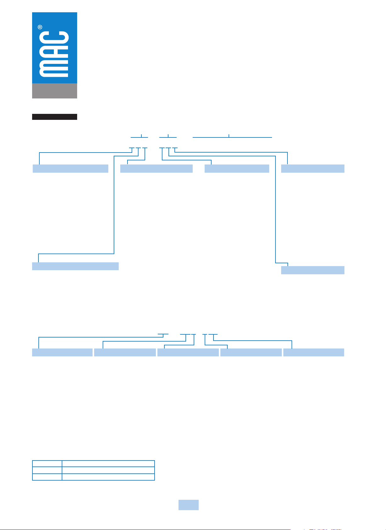
HOW TO ORDER
92B - XXX - XXX - (XX - DXXX - XXX)
BODY
OPTIONS
BASE
OPTIONS
PILOT
VALVE
SEE BELOW
BODY TYPE & EXHAUST OPTIONS
0
Base only
A
Plug-in Standard Exhaust
B*
Non Plug-in with Standard Exhaust
* Use with body electrical option A only
BODY ELECTRICAL OPTIONS
0
Base only
A
No ligth in top
B
With ligth
VALVE FUNCTION
0
Base only
A
Single Operator-Single Pressure
B
Double Operator-Single Pressure
C
Single Operator-Dual Pressure
D
Double Operator -Dual Pressure
E
3 Position Closed Center
F
3 Position Open Center
G
3 Position Single Pressure
Pressure Center
Spool with Memory Spring
L
Single Operator-Single Pressure
N
Single Operator-Dual Pressure
INDIV. BASE CONFIG.
0
Basic Valve
A
Side Ports
B
Bottom Ports (1/8” only)
C
Side & Bottom Ports
(1/8” only)
D
Side in & exhaust Bottom
cylinders (1/8” only)
PORT SIZE - THREAD TYPE
0
Basic Valve
A
1/8” NPTF
B
1/4” NPTF
C
3/8” NPTF
D
1/8” BSPPL
E
1/4” BSPPL
F
3/8” BSPPL
G
1/8” BSPTR
H
1/4” BSPTR
J
3/8” BSPTR
INT. OR EXT. PILOT
0
Basic Valve
Plug-in Internal Pilot Models
A
No light in base
B
With single light in base
C
With double light in base
Plug-in External Pilot Models
D
No light in base
E
With single light in base
F
With double light in base
Non plug-in
G
Internal Pilot
H
External Pilot
If lights are in top body cover, use
option A or D
PILOT VALVE OPTIONS
XX - DXXX - XXX
XX
PILOT EXHAUST
DM
Muffled exhaust
XX
DC VOLTAGE
FR
12 VDC (0.6 W)
X
LEAD WIRE LENGTH
--Plug-in Valve/Base--
P
Plug-in
1
18”
4
48”
2
24”
5
72”
3
36”
6
96”
--Non Plug-in Valve/Base--
O
No wires*
A
18”
E
72”
B
24”
F
96”
C
36”
J
6”**
D
48”
*Used only with BM & BG
electrical connection
** Lead wire length for external
plug-in connectors must be “J”
X
MANUAL OPERATOR
0
No manual operator
1
Recessed Non-locking
operator
2
Recessed Locking operator
3
Non-locking Extended
operator
4
Locking Extended
operator
XX
ELECTRICAL CONN.
--Non Plug-in Valve/Base--
BA
Grommet
BM
Flying leads
BG
Flying leads with ground
CA
Conduit 1/2" NPS
CM
Metal
Conduit 1/2" NPS
CN
Metal
Conduit with
ground1/2" NPS
--Plug-in Valve/Base--
DM
Plug-in
DG
Plug-in with ground
--External Plug-in--
JB
Rectangular plug-in
JM
Rectangular male only
KA
Mini plug-in
KJ
Mini plug-in male only
HOW TO ORDER 92 SERIES FLOW CONTROL MODULE*
NOTE: If a flow control assembly is used with the dual
pressure regulator option, only the flow control on the
“B” end is functional. (Controls both cylinder ports.)
NOTE: Consult the general catalog for regulator and
circuit bar ordering information.
FC 92C-AA
FC 92C-BA
FC 92C-CA
Plug-in flow control assembly single solenoid
Plug-in flow control assembly double solenoid
Non plug-in flow control assembly
*If flow control module is to be installed between valve and base or valve and manifold at the factory,
add -9 after the flow control model number, i.e., FC92C-AA-9. The flow control model number
should follow the valve model number on which it is to be installed.