1_H24维修手册.pdf - 第128页
E d it io n 5 .0 H 24 H ead R ep ai r T r ai n i n g T ext f o r S er vi ce E n g i n e e r Pro p e r D at a M e asu r em en t 7. S e l e c t [OK ] i n t he f ol l ow i ng s c r ee n t o r ec or d t he s er v o c ount of…
Edition 5.0 H24 Head Repair Training Text for Service Engineer
Proper Data Measurement
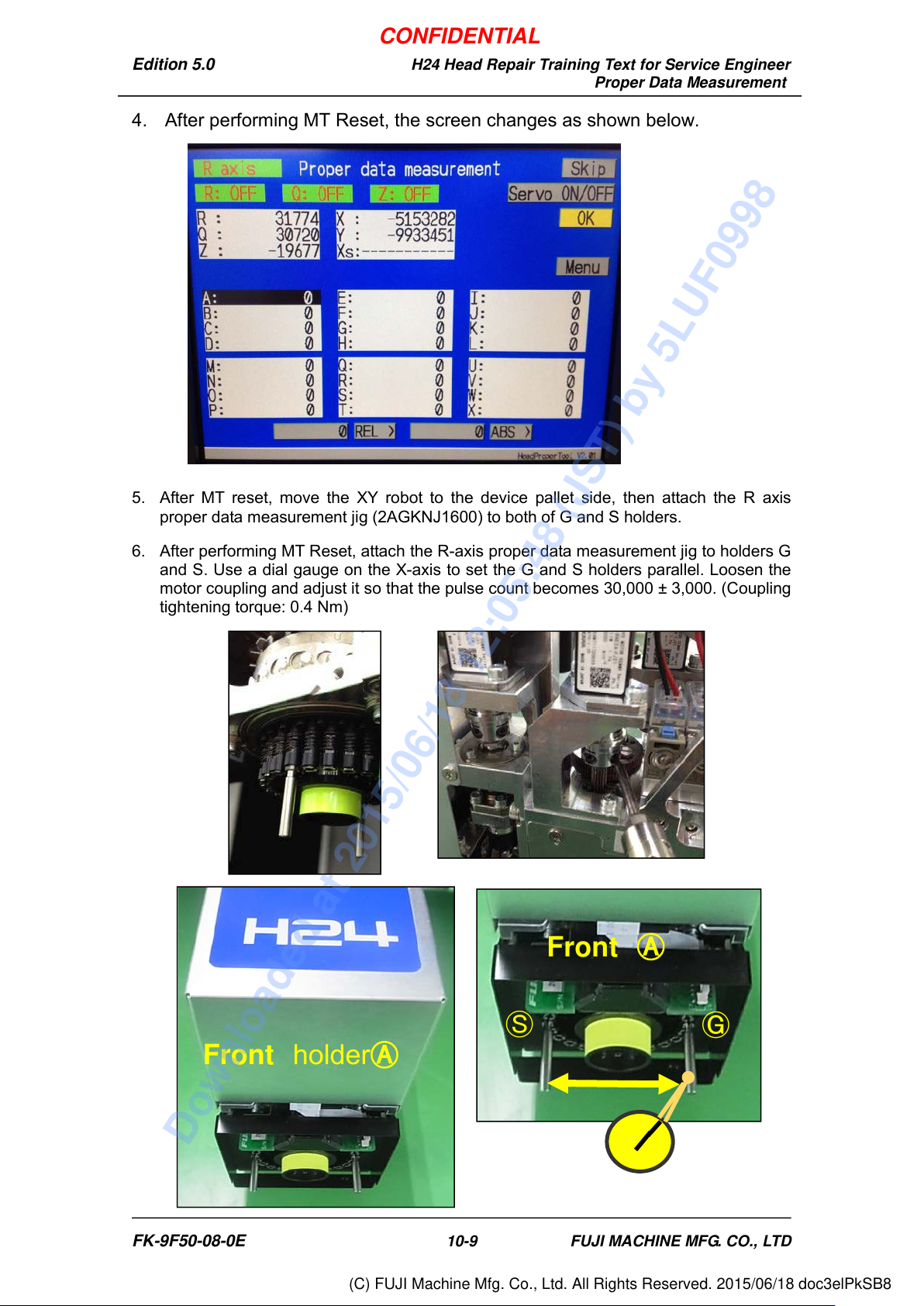
4. After performing MT Reset, the screen changes as shown below.
5. After MT reset, move the XY robot to the device pallet side, then attach the R axis
proper data measurement jig (2AGKNJ1600) to both of G and S holders.
6. After performing MT Reset, attach the R-axis proper data measurement jig to holders G
and S. Use a dial gauge on the X-axis to set the G and S holders parallel. Loosen the
motor coupling and adjust it so that the pulse count becomes 30,000 ± 3,000. (Coupling
tightening torque: 0.4 Nm)
Front holderⒶ
Front Ⓐ
Ⓖ
Ⓢ
FK-9F50-08-0E 10-9 FUJI MACHINE MFG. CO., LTD
CONFIDENTIAL
Downloaded at 2015/06/18 12:05:48 (JST) by 5LUF0998
(C) FUJI Machine Mfg. Co., Ltd. All Rights Reserved. 2015/06/18 doc3elPkSB8
Edition 5.0 H24 Head Repair Training Text for Service Engineer
Proper Data Measurement
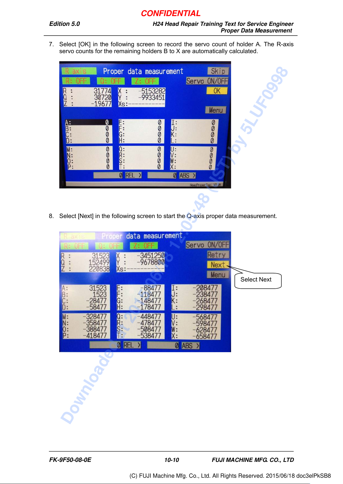
7. Select [OK] in the following screen to record the servo count of holder A. The R-axis
servo counts for the remaining holders B to X are automatically calculated.
8. Select [Next] in the following screen to start the Q-axis proper data measurement.
Select Next
FK-9F50-08-0E 10-10 FUJI MACHINE MFG. CO., LTD
CONFIDENTIAL
Downloaded at 2015/06/18 12:05:48 (JST) by 5LUF0998
(C) FUJI Machine Mfg. Co., Ltd. All Rights Reserved. 2015/06/18 doc3elPkSB8
Edition 5.0 H24 Head Repair Training Text for Service Engineer
Proper Data Measurement
10.6 Q-axis Proper Data Measurement
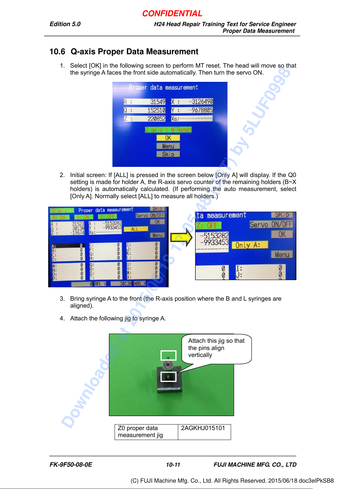
1. Select [OK] in the following screen to perform MT reset. The head will move so that
the syringe A faces the front side automatically. Then turn the servo ON.
2. Initial screen: If [ALL] is pressed in the screen below [Only A] will display. If the Q0
setting is made for holder A, the R-axis servo counter of the remaining holders (B~X
holders) is automatically calculated. (If performing the auto measurement, select
[Only A]. Normally select [ALL] to measure all holders.)
3. Bring syringe A to the front (the R-axis position where the B and L syringes are
aligned).
4. Attach the following jig to syringe A.
Z0 proper data
measurement jig
2AGKHJ015101
Attach this jig so that
the pins align
vertically
FK-9F50-08-0E 10-11 FUJI MACHINE MFG. CO., LTD
CONFIDENTIAL
Downloaded at 2015/06/18 12:05:48 (JST) by 5LUF0998
(C) FUJI Machine Mfg. Co., Ltd. All Rights Reserved. 2015/06/18 doc3elPkSB8