1_H24维修手册.pdf - 第75页
Edi t i on 5 .0 H 24 H e ad R e p ai r T r a i n i n g T ext f o r S er vi ce E n g i n eer s A dj us t i n g t h e N o z z l e L o w er i n g L ever C h eck S en so r a nd M ea su r i n g t h e A i r P r essu r e 9. Cl …
Edition 5.0
H24 Head Repair Training Text for Service Engineers
Adjusting the Nozzle Lowering Lever Check Sensor and Measuring the Air Pressure
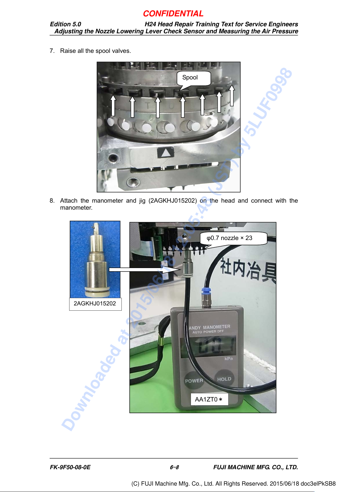
7. Raise all the spool valves.
8. Attach the manometer and jig (2AGKHJ015202) on the head and connect with the
manometer.
2AGKHJ015202
AA1ZT0
*
φ0.7 nozzle × 23
Spool
FK-9F50-08-0E
6-8
FUJI MACHINE MFG. CO., LTD.
CONFIDENTIAL
Downloaded at 2015/06/18 12:05:48 (JST) by 5LUF0998
(C) FUJI Machine Mfg. Co., Ltd. All Rights Reserved. 2015/06/18 doc3elPkSB8
Edition 5.0
H24 Head Repair Training Text for Service Engineers
Adjusting the Nozzle Lowering Lever Check Sensor and Measuring the Air Pressure
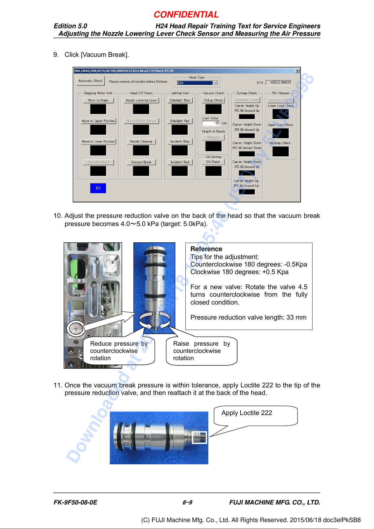
9. Click [Vacuum Break].
10. Adjust the pressure reduction valve on the back of the head so that the vacuum break
pressure becomes 4.0~5.0 kPa (target: 5.0kPa).
11. Once the vacuum break pressure is within tolerance, apply Loctite 222 to the tip of the
pressure reduction valve, and then reattach it at the back of the head.
Apply Loctite 222
Reduce pressure by
counterclockwise
rotation
Raise pressure by
counterclockwise
rotation
Reference
Tips for the adjustment:
Counterclockwise 180 degrees: -0.5Kpa
Clockwise 180 degrees: +0.5 Kpa
For a new valve: Rotate the valve 4.5
turns counterclockwise from the fully
closed condition.
Pressure reduction valve length: 33 mm
FK-9F50-08-0E
6-9
FUJI MACHINE MFG. CO., LTD.
CONFIDENTIAL
Downloaded at 2015/06/18 12:05:48 (JST) by 5LUF0998
(C) FUJI Machine Mfg. Co., Ltd. All Rights Reserved. 2015/06/18 doc3elPkSB8
Edition 5.0
H24 Head Repair Training Text for Service Engineers
Adjusting the Nozzle Lowering Lever Check Sensor and Measuring the Air Pressure
6.3 Airflow Measurement
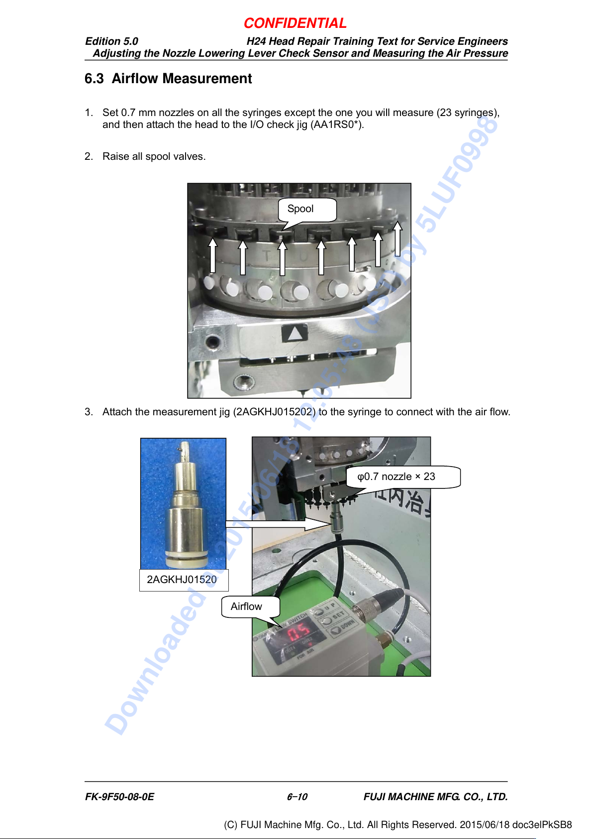
1. Set 0.7 mm nozzles on all the syringes except the one you will measure (23 syringes),
and then attach the head to the I/O check jig (AA1RS0*).
2. Raise all spool valves.
3. Attach the measurement jig (2AGKHJ015202) to the syringe to connect with the air flow.
Spool
Airflow
2AGKHJ01520
φ0.7 nozzle × 23
FK-9F50-08-0E
6-10
FUJI MACHINE MFG. CO., LTD.
CONFIDENTIAL
Downloaded at 2015/06/18 12:05:48 (JST) by 5LUF0998
(C) FUJI Machine Mfg. Co., Ltd. All Rights Reserved. 2015/06/18 doc3elPkSB8